Construction steel structure glue-joint technique
A technology of structural adhesive and construction steel, which is applied in building construction, construction, measuring devices, etc., to achieve the effect of reducing production cost, improving production efficiency, and good shear resistance.
- Summary
- Abstract
- Description
- Claims
- Application Information
AI Technical Summary
Problems solved by technology
Method used
Image

Examples
example 1
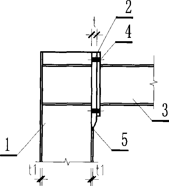
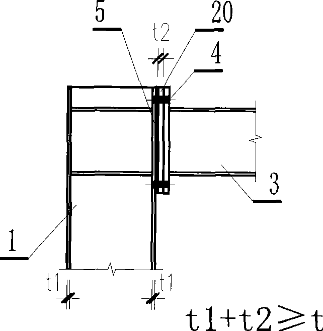
[0016] Such as figure 1 , figure 2 As shown, in construction engineering, the column 1 and the beam 3 usually used are welded by three steel plates, and their cross-sectional shape is generally H-shaped. Existing technologies such as figure 1 As shown, at the connection between the column and the beam, it is necessary to cut and process a thickened column flange plate 2, and a hole corresponding to the size and shape of the flange plate should also be cut on the column 1, and then the thickened flange plate The plate is welded on the column 1 here, and the weld needs to be ultrasonically inspected. Use high-strength bolts to connect the flange plate 2 welded on the column 1 and the end plate 4 welded on the beam 3, so that the column and the beam are connected together. The characteristics of the present invention are as figure 2 As shown, the thickened flange plate 20(t 2 ) and the flange plate (joint part) of steel column 1 should be straight on the surface, and then ...
example 2
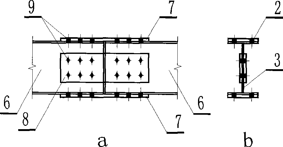
[0018] Such as image 3 , Figure 4 As shown, the two beams 6 are also H-shaped components welded by three steel plates. In the figure, a shows the schematic diagram of the axial connection relationship between the two beams; in the figure, b shows the cross-sectional H-shaped schematic diagram of the beams. Existing technologies such as image 3 As shown, the two steel beams 6 are connected together by the flange plate splicing plate 7, the web splicing plate 8, and the high-strength bolts 9; the two steel beams 6 can also be connected together by riveting. The present invention is for the connection of this two beams, as Figure 4 As shown, its structural feature is that the two steel beams 6 are directly glued and connected together by using the flange plate splicing plate 7 and the web splicing plate 8 through the adhesive layer 10 . (the specific implementation method is the same as embodiment 1)
example 3
[0020] For the parts with insufficient strength of the combined steel plate type steel structure, it is necessary to set up reinforcement members. Existing technologies such as Figure 5 Shown, be welded on the insufficient strength position of original steel component 11 with reinforced steel plate 12, its weld seam is represented by 13; The present invention is as Image 6 As shown, the reinforced steel plate 12 is strengthened and connected to the original steel member 11 with an adhesive layer 14, which is convenient and practical (the specific implementation method is the same as that of embodiment 1).
PUM
 Abstract
Description
Claims
Application Information
 - R&D
- Intellectual Property
- Life Sciences
- Materials
- Tech Scout
- Unparalleled Data Quality
- Higher Quality Content
- 60% Fewer Hallucinations
Browse by: Latest US Patents, China's latest patents, Technical Efficacy Thesaurus, Application Domain, Technology Topic, Popular Technical Reports.
© 2025 PatSnap. All rights reserved.Legal|Privacy policy|Modern Slavery Act Transparency Statement|Sitemap|About US| Contact US: help@patsnap.com