A hollow buffer structure for artificial prosthesis

A buffer structure, artificial prosthesis technology, applied in the field of artificial prosthesis, can solve the problems of strength reduction, prosthesis structure rigidity and strength contradiction, etc., to achieve the effect of improving the degree of mechanical stimulation, avoiding reconstruction and loss, and reducing the strength requirements

Active Publication Date: 2017-12-26
深圳协同创新高科技发展有限公司
View PDF6 Cites 0 Cited by
  • Summary
  • Abstract
  • Description
  • Claims
  • Application Information

AI Technical Summary

Problems solved by technology

However, the increase in the porosity of the prosthesis will inevitably lead to a decrease in strength, so the core problem facing the design of low modulus prosthesis is the contradiction between the structural stiffness and strength of the prosthesis

Method used


Image

  • A hollow buffer structure for artificial prosthesis
  • A hollow buffer structure for artificial prosthesis
  • A hollow buffer structure for artificial prosthesis

Examples


Embodiment 1

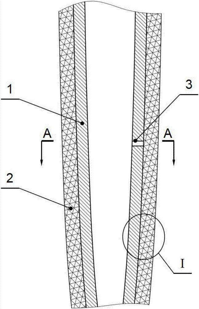
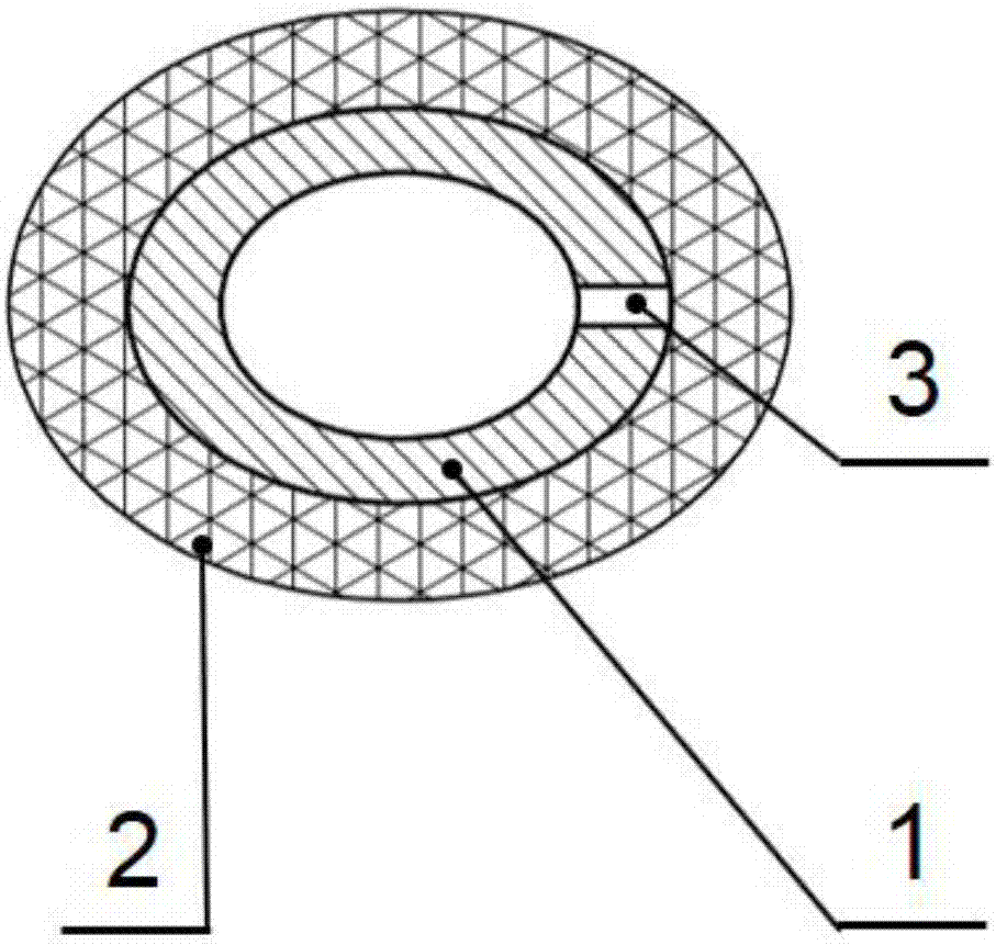
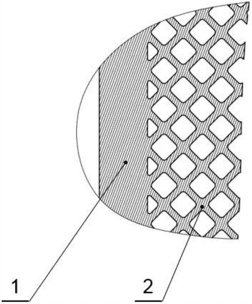
[0035] Embodiment 1, artificial hip joint femoral handle with hollow buffer structure: as Figure 4 with Figure 5 As shown, the artificial hip joint femoral stem mainly includes a neck solid part 4 and a hollow buffer part 5 , wherein the hollow buffer part 5 includes a closed thin-walled part 1 and a buffer structure 2 . The closed thin-walled part 1 is a closed hollow structure, which is located inside the femoral stem of the artificial hip joint and is wrapped by the buffer structure 2; the buffer structure 2 is composed of a three-dimensional grid-like porous structure, which is filled outside the closed thin-walled part 1. The artificial hip joint within the outer contour of the femoral stem. There is a small through hole 3 on the top of the closed thin-walled part 1, the diameter of which is 1mm, and the small through-hole 3 is connected with the positioning hole of the femoral stem of the artificial hip joint to discharge the residual powder inside the closed thin-wal...

Embodiment 2

[0041] Embodiment 2: tibial tray with hollow cushioning structure: as Image 6 with Figure 7 As shown, the tibial tray includes a tray solid part 6 and a hollow buffer part 5 , wherein the hollow buffer part 5 includes a closed thin-walled part 1 and a buffer structure 2 . The closed thin-walled part 1 is a closed hollow structure, which is located at the lower part of the tibial tray and wrapped by the buffer structure 2; the buffer structure 2 is composed of a three-dimensional grid-like porous structure, which is filled outside the closed thin-walled part 1 and inside the outer contour of the tibial tray . There is a small through hole 3 on the top of the closed thin-walled part 1, the diameter of which is 1mm, and the small through hole 3 is located at the center of the bottom of the tibial tray to discharge the residual powder inside the closed thin-walled part 1.

[0042] The shape of the closed thin-walled part 1 of the tibial tray is a body of revolution developed a...


PUM


Abstract

The invention relates to a hollow buffer structure for an artificial prosthesis. The hollow buffer structure comprises a closed thin wall part and a buffer structure outside the closed thin wall part, wherein the closed thin wall part is of a closed hollow structure, is located in the artificial prosthesis and is packaged by the buffer structure; the buffer structure is of a three-dimensional grid shape and fills the space outside the closed thin wall part and inside the outer contour of the artificial prosthesis; and a small through hole for discharging residual powder in the closed thin wall part is formed in the closed thin wall part. The closed thin wall part plays a main supporting role and needs to meet strength requirements, and the buffer structure plays a role of promoting the conduction of stress from the artificial prosthesis to bones. On the premise that the strength requirements are met, the hollow buffer structure manufactured by virtue of an additional material manufacturing technique is capable of promoting the conduction of the stress to the bones, so that the bone loss and loosening caused by stress shielding are avoided, the stability of the implanted artificial prosthesis can be improved, and the service life of the implanted artificial prosthesis can be prolonged.

Description

technical field [0001] The invention belongs to the technical field of artificial prosthesis, and in particular relates to a hollow buffer structure for artificial prosthesis. Background technique [0002] Artificial prosthesis is the ultimate means of treating various bone defects or severe joint diseases. Existing artificial prosthesis products are mainly made of metal materials, which need to be carried in the human body for a long time after implantation. However, the rigidity of the metal prosthesis is much greater than that of human bones, and it will cause a significant stress shielding effect after implantation. The prosthesis bears more stress while the surrounding bone bears less stress. In this case, the bone will remodel according to the stress it receives, and the bone tissue will shrink when the stress is reduced, causing long-term loosening of the prosthesis. After the prosthesis is loosened, the implementation of revision surgery will not only bring additio...

Claims


Application Information

Patent Timeline
Patent Type & Authority Patents(China)
IPC IPC(8): A61F2/28A61F2/36
CPCA61F2/28A61F2/3662A61F2/3672A61F2002/2825A61F2002/2892A61F2002/30593A61F2002/368
Inventor 王玲孙畅宁李涤尘靳忠民康建峰
Owner 深圳协同创新高科技发展有限公司
Why Eureka
Try Eureka