Connector and its making method

A technology of connectors and contacts, applied in the field of metal conductive terminal connectors

Inactive Publication Date: 2010-05-12
KS TERMINALS INC
View PDF10 Cites 0 Cited by
  • Summary
  • Abstract
  • Description
  • Claims
  • Application Information

AI Technical Summary

Problems solved by technology

The low-melting-point metal material is fitted into the longitudinal slot of the C-shaped part and the insulating sleeve is sleeved on the outside of the C-shaped part and the low-melting-point metal material

Method used


Image

  • Connector and its making method
  • Connector and its making method
  • Connector and its making method

Examples


Embodiment Construction

[0046] Since the present invention discloses a connector and its manufacturing method, the basic components and combination principles of some wire structures used in it have been disclosed in detail in the prior art, so the following description will not be fully described. At the same time, the following diagrams are used to express the structural diagrams related to the features of the present invention, and do not and need not be completely drawn according to the actual size.

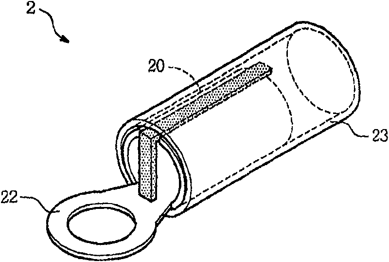
[0047] See figure 2 and image 3 , a preferred embodiment of the connector of the present invention. In this preferred embodiment, the connector 2 includes a metal conductive terminal 20 , a low melting point metal material 212 and an insulating sleeve 23 .

[0048] The metal conductive terminal 20 mainly includes a first end 21 and a second end 22 opposite to the first end 21 , the first end 21 is used to connect with an electric wire, and the second end 22 is used to connect to an external cond...


PUM


Abstract

A connector and its manufacturing methods. The connector includes a metal conductive terminal, a low melting point metal substance and an insulation casing; one end of the metal conductive terminal bends to form a vertical slotted C-type portion in order to accommodate a wire to insert, another end is used to connect the external conductive junction point; the low melting point metal substance istabled in the vertical slot of the C-type portion and the insulation casing is coverd on the outside of the C-type portion and the low melting point metal substance; When heating up the low melting point metal substance and the insulation casing, the low melting point metal substance is melted to connect with the C-type portion and the wire conductive core in the C-type portion, while the insulation casing properly contracts to coat the metallic conductive terminals and the wires, in order to complete the combination of the connector and the wire.

Description

technical field [0001] The invention relates to a connector, in particular to a metal conductive terminal connector. After the connector is joined with a wire, the conductive core of the wire is not exposed and has an insulating effect. Background technique [0002] The metal conductive terminal connector of the prior art is mainly disclosed in US Publication No. US5137478, please refer to figure 1 . figure 1 Among them, the end 12 of the connector 10 is bent into a semicircular structure 13, and a layer of conductive adhesive 14 is used to adhere the semicircular sheet of low melting point metal material 15. Place a conductive core 17 exposed outside the insulating skin 16 on the semicircular sheet-shaped low-melting-point metal material 15, apply external heat from the connector end 12, and connect the semi-circular sheet-shaped low-melting-point metal material 15 to the The device end 12 and the conductive core 17 are fused and consolidated into one body due to heating,...

Claims


Application Information

Patent Timeline
Patent Type & Authority Patents(China)
IPC IPC(8): H01R4/02H01R4/70H01R11/11H01R43/02
Inventor 徐乙辰
Owner KS TERMINALS INC
Why Eureka
Try Eureka