Cell type electronic equipment
An electronic equipment, unit-type technology, applied in the direction of electrical program control, comprehensive factory control, comprehensive factory control, etc., can solve the problems of slow unit startup time, long waiting time, assembly errors, etc., and achieve the reduction of hardware components and easy assembly. performance improvement and software simplification
- Summary
- Abstract
- Description
- Claims
- Application Information
AI Technical Summary
Problems solved by technology
Method used
Image


Examples
Embodiment approach 1
[0034] Next, use figure 1 and figure 2 , The first embodiment of the present invention will be described.
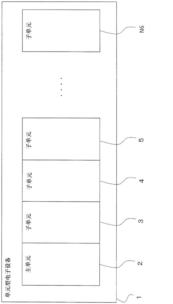
[0035] figure 1 It is a schematic configuration diagram showing an example of an arrangement of a master unit as a master unit and a plurality of sub-units as slave units in a unit-type electronic device. As shown in the figure, in the unit-type electronic device 1, the The master unit 2 is located at the left end of the figure, and a plurality of subunits 3, 4, 5,... N6 as slave units are sequentially located on the right side of the figure of the master unit 2 to be arranged separately.
[0036] in figure 1 Among them, a plurality of sub-units 3, 4, 5, ... N6 as slave units are, for example, sub-units for digital input and output, sub-units for analog input, collection of measured quantities such as power measurement and collected Multiple measurement sub-units, etc., where the measured quantity data (measured quantity data) is stored.
[0037] The main unit 2 as the mai...
Embodiment approach 2
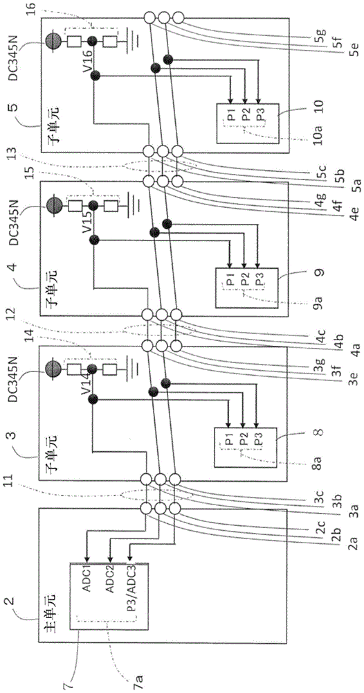
[0056] Next, use image 3 The second embodiment of the present invention will be described. image 3 It is a block diagram showing another example of the connection method between the main unit and the multiple sub-units and the connection method in each unit. In addition, the schematic structure is the same as that of Embodiment 1. figure 1 Similarly, this schematic structure shows an example of an arrangement of a master unit as a master unit and a plurality of subunits as a slave unit in a unit-type electronic device.
[0057] In the second embodiment, compared with the first embodiment, it is possible to further reduce the number of bus lines 11, 12, and 13 for connection between units.
[0058] in image 3 In the main unit 2, there is a microcomputer 7 and a connection bus 11, and the subunit 3 has a microcomputer 8, a characteristic voltage setting unit 14, a connection bus 12, and a DC power supply DC345N. The subunit 4 and the subunit 5 have the same structure as the subun...
Embodiment approach 3
[0062] Next, use Figure 4 ~ Figure 7 The third embodiment of the present invention will be described. Figure 4 It is a schematic configuration diagram showing an example of an arrangement of a master unit as a master unit, a communication unit as a master unit, and a plurality of subunits as a slave unit in a unit-type electronic device, Figure 5 It is a structural diagram showing an example of the connection method between the main unit, the communication unit and the multiple sub-units and the connection method in each unit, Image 6 It is an operation explanatory diagram that illustrates the operation of the flowchart, Figure 7 It is an operation explanatory diagram showing an example of the operation in a time sequence chart.
[0063] This embodiment is an example in which the method of embodiment 1 or embodiment 2 can be used to arbitrarily set the connection position of the communication unit as the master control unit, as a method for each sub-unit to identify any connec...
PUM
 Abstract
Description
Claims
Application Information
 - R&D
- Intellectual Property
- Life Sciences
- Materials
- Tech Scout
- Unparalleled Data Quality
- Higher Quality Content
- 60% Fewer Hallucinations
Browse by: Latest US Patents, China's latest patents, Technical Efficacy Thesaurus, Application Domain, Technology Topic, Popular Technical Reports.
© 2025 PatSnap. All rights reserved.Legal|Privacy policy|Modern Slavery Act Transparency Statement|Sitemap|About US| Contact US: help@patsnap.com