Lamp post system using multi-groove mounting structure
A technology for installing structures and light poles, which is applied to the components, lighting devices, lighting devices, etc. of lighting devices, and can solve the problems of limiting the number of functional parts installed, fasteners are prone to rust and failure, and the hoop is easy to loosen and rotate. , to achieve the effect of improving connection stability and reliability, improving installation flexibility, and improving aesthetics
- Summary
- Abstract
- Description
- Claims
- Application Information
AI Technical Summary
Problems solved by technology
Method used
Image
Examples
Embodiment 1
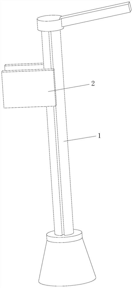
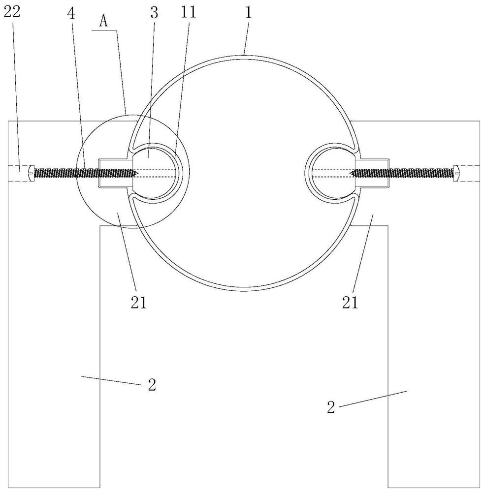
[0034] Such as Figure 1 to Figure 3 As shown, the light pole system adopting a multi-groove installation structure in this embodiment includes a light pole main body 1 and more than one functional part 2. The light pole main body 1 has more than two installation grooves extending along the length direction, and each functional part 2. More than one connecting piece 3 is connected through a detachable connecting mechanism, and each connecting piece 3 is installed in the installation groove in a detachable manner. The light pole system adopts the main body 1 of the light pole with a mounting groove, and the connecting part 3 connected with the functional part 2 is detachably installed in the mounting groove. Compared with the traditional installation method, the connecting part 3 is hidden in the mounting groove In the middle, the aesthetics can be improved, and the matching structure of the connecting piece 3 placed in the installation groove can play a certain positioning rol...
Embodiment 2
[0044] The light pole system using the multi-groove installation structure of this embodiment is basically the same as that of Embodiment 1, the main difference is that, as Figure 4 with Figure 5 As shown, in this embodiment, the light pole main body 1 is provided with four inner expansion grooves 11, and the cross-sections of the bottom groove bottom and the top groove body of the inner expansion grooves 11 are rectangular, and each inner expansion groove 11 is correspondingly installed with one Function 2. The connector 3 is an expansion member that can be inserted into the inner expansion groove 11 from the notch of the inner expansion groove 11 and can be positioned between the inner walls of the inner expansion groove 11 through rotation and expansion after insertion. The tensioning member of this embodiment can be a strip, and it is preferable to arrange a tensioning curved surface at both ends of the strip to realize gradual expansion. Specifically, the tensioning me...
Embodiment 3
[0047] The light pole system using the multi-groove installation structure of this embodiment is basically the same as that of Embodiment 1, the main difference is that, as Image 6 with Figure 7 As shown, in this embodiment, the light pole main body 1 is provided with three inner expansion grooves 11, and the inner expansion grooves 11 are dovetail grooves. Each inner expansion groove 11 is correspondingly installed with a functional part 2 .
PUM
 Abstract
Description
Claims
Application Information
 - R&D
- Intellectual Property
- Life Sciences
- Materials
- Tech Scout
- Unparalleled Data Quality
- Higher Quality Content
- 60% Fewer Hallucinations
Browse by: Latest US Patents, China's latest patents, Technical Efficacy Thesaurus, Application Domain, Technology Topic, Popular Technical Reports.
© 2025 PatSnap. All rights reserved.Legal|Privacy policy|Modern Slavery Act Transparency Statement|Sitemap|About US| Contact US: help@patsnap.com


