Unit-type electronic equipment
A technology of electronic equipment and unit type, applied in the direction of electrical program control, comprehensive factory control, instruments, etc., can solve the problems of slow unit start-up time, assembly errors, long waiting time, etc., and achieve reduction of hardware components, simplification of software, assembly Effect of Ease of Improvement
- Summary
- Abstract
- Description
- Claims
- Application Information
AI Technical Summary
Problems solved by technology
Method used
Image
Examples
Embodiment approach 1
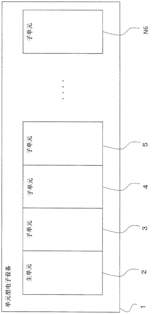
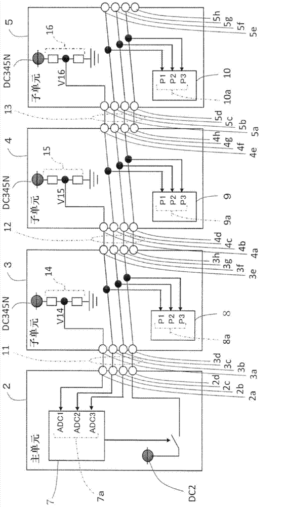
[0034] Next, use figure 1 and figure 2 , The first embodiment of the present invention will be described.
[0035] figure 1 It is a schematic configuration diagram showing an example of an arrangement of a master unit as a master unit and a plurality of subunits as a slave unit in a unit-type electronic device. As shown in the figure, in the unit-type electronic device 1, as the master unit The master unit 2 is located at the left end of the figure, and a plurality of subunits 3, 4, 5,... N6 as slave units are sequentially located on the right side of the figure of the master unit 2 to be arranged separately.
[0036] in figure 1 Among them, a plurality of sub-units 3, 4, 5, ... N6 as slave units are, for example, sub-units for digital input and output, sub-units for analog input, collection of measured quantities such as power measurement and collected Multiple measurement sub-units, etc., where the measured quantity data (measured quantity data) is stored.
[0037] The main un...
Embodiment approach 2
[0056] Next, use image 3 The second embodiment of the present invention will be described. image 3 It is a block diagram showing another example of the connection method between the main unit and the plurality of sub-units and the connection method in each unit. In addition, the schematic structure is the same as that of Embodiment 1. figure 1 Similarly, this schematic structure shows an example of an arrangement of a master unit as a master unit and a plurality of subunits as a slave unit in a unit-type electronic device.
[0057] In the second embodiment, compared with the first embodiment, it is possible to further reduce the number of bus lines 11, 12, and 13 for connection between units.
[0058] in image 3 In the main unit 2, there is a microcomputer 7 and a connection bus 11, and the subunit 3 has a microcomputer 8, a characteristic voltage setting unit 14, a connection bus 12, and a DC power supply DC345N. The subunit 4 and the subunit 5 have the same structure as the s...
Embodiment approach 3
[0062] Next, use Figure 4 ~ Figure 7 The third embodiment of the present invention will be described. Figure 4 It is a schematic configuration diagram showing an example of an arrangement of a master unit as a master control unit, a communication unit as a master control unit, and a plurality of subunits as a slave unit in a unit-type electronic device, Figure 5 It is a structural diagram showing an example of the connection method between the main unit, the communication unit and the multiple sub-units and the connection method in each unit, Image 6 It is an operation explanatory diagram that illustrates the operation of the flowchart, Figure 7 It is an operation explanatory diagram showing an example of the operation in a time sequence chart.
[0063] This embodiment is an example in which the method of embodiment 1 or embodiment 2 can be used to arbitrarily set the connection position of the communication unit as the main control unit, as a method for each sub-unit to ident...
PUM
 Abstract
Description
Claims
Application Information
 - R&D
- Intellectual Property
- Life Sciences
- Materials
- Tech Scout
- Unparalleled Data Quality
- Higher Quality Content
- 60% Fewer Hallucinations
Browse by: Latest US Patents, China's latest patents, Technical Efficacy Thesaurus, Application Domain, Technology Topic, Popular Technical Reports.
© 2025 PatSnap. All rights reserved.Legal|Privacy policy|Modern Slavery Act Transparency Statement|Sitemap|About US| Contact US: help@patsnap.com


