
Method of manufacturing wiring substrate

A technology of a wiring substrate and a manufacturing method, which can be used in the manufacture of printed circuits, semiconductor/solid-state device manufacture, and catalyst-applied resists, etc., and can solve the problems of numerous manufacturing processes and the like

Inactive Publication Date: 2007-09-12
SEIKO EPSON CORP
View PDF1 Cites 4 Cited by
  • Summary
  • Abstract
  • Description
  • Claims
  • Application Information

AI Technical Summary

Problems solved by technology

[0003] According to this method, since a step of finally removing the plating resist layer is required, there is a problem that the manufacturing process is complicated. Therefore, a method of depositing a metal layer without using a plating resist layer has attracted attention.

Method used


Image

  • Method of manufacturing wiring substrate
  • Method of manufacturing wiring substrate
  • Method of manufacturing wiring substrate

Examples


experiment example

[0053] 3.1. The first experimental example

[0054] A wiring board is formed by the method of manufacturing a wiring board according to this embodiment.

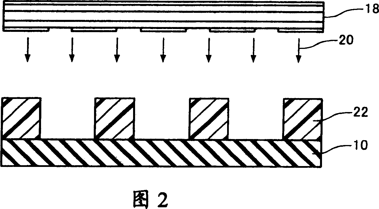
[0055] (1) Form a photoresist film (photoresist film, photoresist film) on a glass substrate, and then, by direct writing, expose the photoresist film in the form of a straight line with a pitch of about 1 μm and a width of about 200 nm , and developed to form a photoresist layer having linear lines with a width of approximately 800 nm and stripe-shaped openings with an interval of approximately 200 nm.

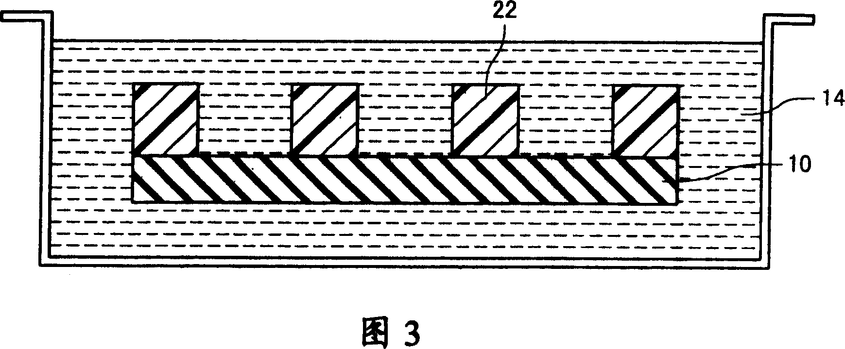
[0056] (2) Next, the glass substrate was cut into a square of 1×1 cm, and immersed in a cationic surfactant solution (FPD condiishyona manufactured by Technic Japan Co., Ltd., FPD conditioner manufactured by Technic Japan Co., Ltd.), and then, The glass substrate is fully washed with water.

[0057] (3) Next, a catalyst solution was prepared by the following procedure. First, a mixed solution of hydrochloric acid, hydrog...


PUM


Abstract

A method of manufacturing an interconnect substrate by electroless plating which causes a metal to be deposited without using a plating resist, the method including: (a) immersing a substrate in a catalyst solution including palladium, hydrogen peroxide, and hydrochloric acid to form a catalyst layer on the substrate; and (b) depositing a metal on the catalyst layer by immersing the substrate in an electroless plating solution to form a metal layer.

Description

technical field [0001] The present invention relates to a method of manufacturing a wiring substrate. Background technique [0002] In recent years, as the speed and density of electronic devices continue to increase, an additive method (additive method) has attracted attention as a method of manufacturing a wiring board. In the additive method, there is known a method of patterning a photoresist (photoresist) provided on a substrate to form a plating resist layer, and performing plating treatment on the openings of the plating resist layer, so that the metal layer Precipitate. Japanese Patent Application Laid-Open No. 10-140364 discloses an electroless plating solution in which plating is performed using a plating resist in this way. [0003] According to this method, since a step of finally removing the plating resist layer is required, there is a problem that the manufacturing process is complicated. Therefore, a method of depositing a metal layer without using a platin...

Claims


Application Information

Patent Timeline
IPC IPC(8): H05K3/18C23C18/32
CPCH05K2203/0565C23C18/36C23C18/2086H05K3/184C23C18/1893H01L21/4846C23C18/30
Inventor 木村里至降旗荣道
Owner SEIKO EPSON CORP
Learn More