Eureka AIR delivers breakthrough ideas for toughest innovation challenges, trusted by R&D personnel around the world.

Vacuum inner film coating machine and using method thereof

A coating machine and vacuum technology, applied in the field of vacuum internal coating machine, can solve the problems of high machine cost, long working cycle, low production efficiency, etc., and achieve the effect of convenient equipment maintenance, high production efficiency and energy saving

Inactive Publication Date: 2007-09-12
惠州市惠阳区新田玻璃工艺制品有限公司
View PDF0 Cites 2 Cited by
  • Summary
  • Abstract
  • Description
  • Claims
  • Application Information

AI Technical Summary

Problems solved by technology

[0002] Due to the complex structure and bulky appearance of the current general vacuum inner coating machine, the cost of the machine is very high, and because these vacuum inner coating machines have many operating steps, and the time to complete the inner coating is long, the production efficiency is low. In mass production, the production capacity will be insufficient. Generally, the operation steps of the vacuum internal coating machine are: first turn on the diffusion pump to heat for 1.5 to 2 hours, then turn on the rough pump to start the air extraction process, and then turn on the Roots pump, followed by Open the rough pumping valve and the fine pumping valve, and then start the evaporation process. After the evaporation is completed, rotate the workpiece, take out the workpiece that has been coated, and then continue the deflation process
[0003] The general vacuum internal coating machine needs to turn on the diffusion pump to heat for 1.5 to 2 hours, and then turn on the rough pump, Roots pump and other operations in turn. The operation steps are cumbersome and the working cycle is relatively long. The maintenance pump and the diffusion pump must be turned on all the time, which wastes electric energy and is prone to dangerous accidents

Method used

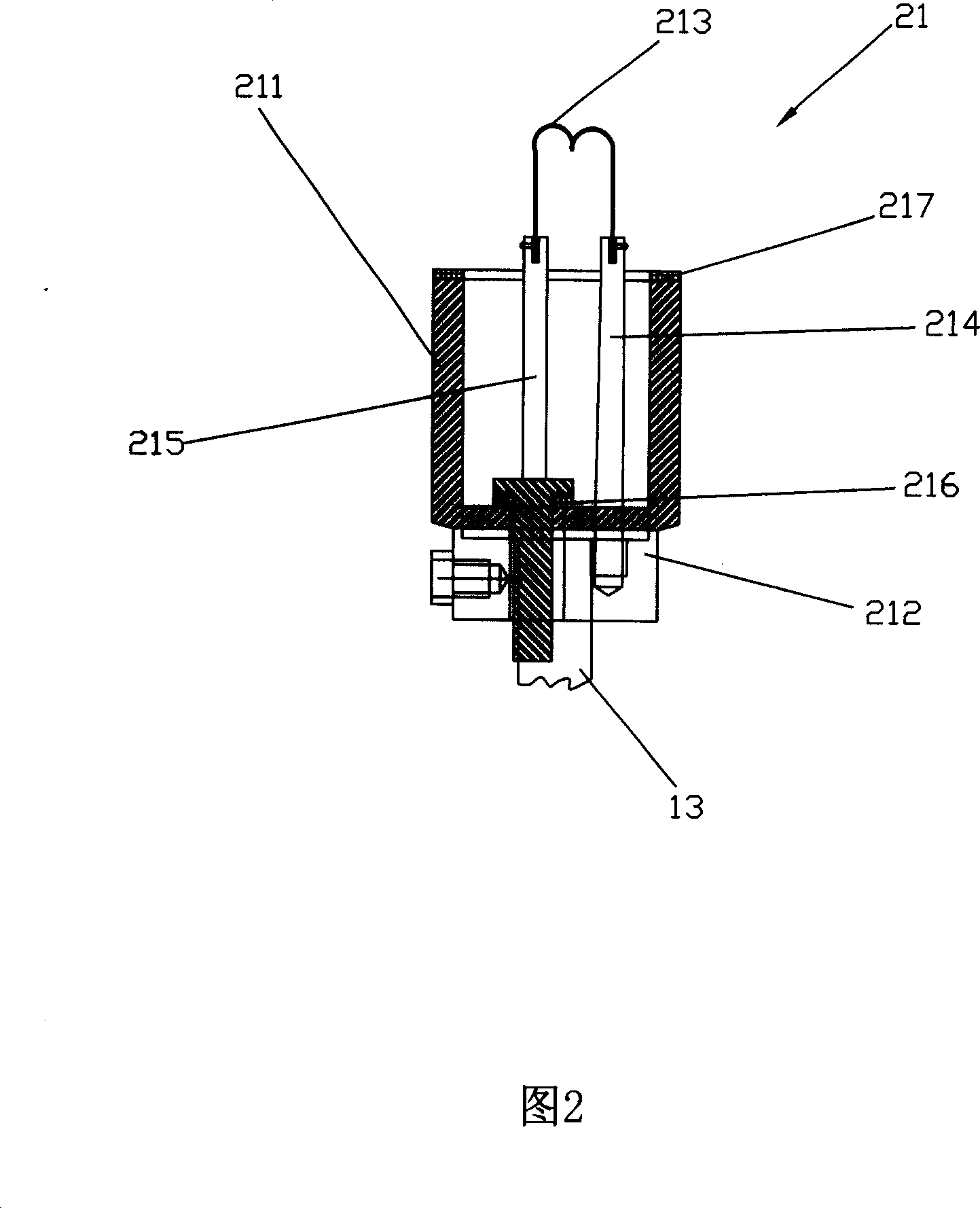
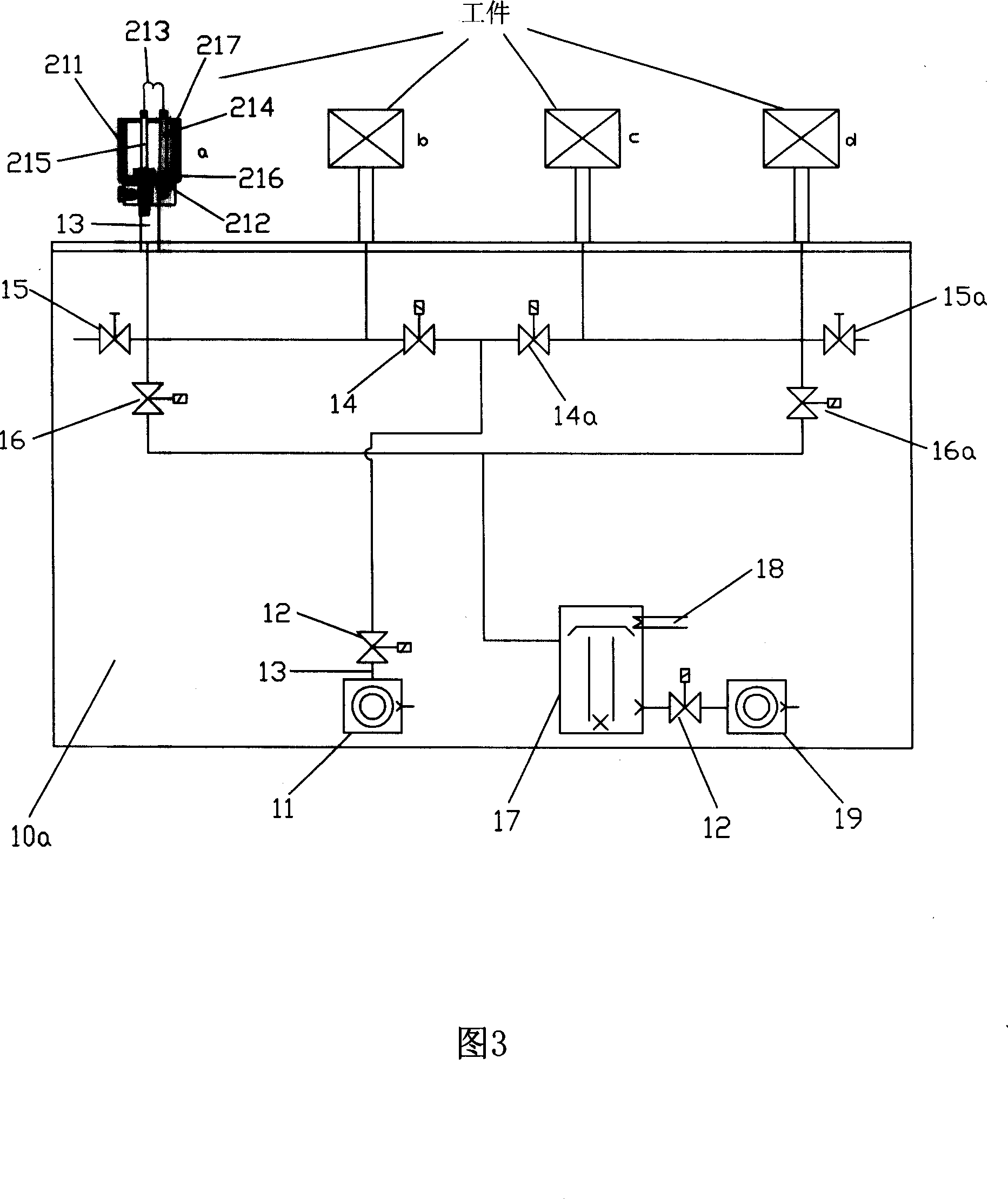

Image

  • Vacuum inner film coating machine and using method thereof
  • Vacuum inner film coating machine and using method thereof
  • Vacuum inner film coating machine and using method thereof

Examples


Embodiment 2

[0059] Implementation principle of embodiment two: products a and b are a group, and the high-vacuum butterfly valve (14) of the rough pumping effect is exhausted to 10 × 10 by the mechanical pump (11) earlier. -0 Pa, then close the high-vacuum butterfly valve (14), open the high-vacuum electromagnetic valve (16) of fine pumping effect to be pumped by the direct-connected mechanical pump (19); simultaneously open the high-vacuum butterfly valve (14a) of product c and d, when the product The air pressure in a and b drops to 5×10 -2 At Pa, turn on the power switch (22), energize the tungsten wire (213) of the evaporation system (20) of the products a and b, and start evaporation. After the vapor deposition is completed, close the high vacuum solenoid valve (16), open the inflation valve (15), and take off the products a and b that have completed the inner coating process; then switch the valve, close the high vacuum butterfly valve (14a), and open the high vacuum valve Vacuum s...


PUM


Abstract

This invention relates to a vacuum internal film-plating machine used in small spherical or cup devices and its application method including a vacuumizing system set with an air pipe connected with a pump controlling the vacuum system and an electric system controlling the valve, said vacuum system is connected with an evaporation system via the pipe, which includes a supply switch and resistance evaporation source composed of a vacuum cavity, a base with a pump-nozzle and tungsten filament for evaporation, in which, Mo positive and negative are fixed on the base, one end of the filament is fixed on the Mo positive and the other end is fixed on the negative and both electrodes pass the base to connect with the supply switch by lead.

Description

Technical field: [0001] The invention relates to an inner coating machine, in particular to a vacuum inner coating machine for spherical or cup-shaped small devices and its application method. Background technique: [0002] Due to the complex structure and bulky appearance of the current general vacuum inner coating machine, the cost of the machine is very high, and because these vacuum inner coating machines have many operating steps, and the time to complete the inner coating is long, the production efficiency is low. In mass production, the production capacity will be insufficient. Generally, the operation steps of the vacuum internal coating machine are: first turn on the diffusion pump to heat for 1.5 to 2 hours, then turn on the rough pump to start the air extraction process, and then turn on the Roots pump, followed by Open the rough pumping valve and the fine pumping valve, and then start the evaporation process. After the evaporation is completed, rotate the workpie...

Claims


Application Information

Patent Timeline
Patent Type & Authority Applications(China)
IPC IPC(8): C23C14/24C23C14/54
Inventor 黄川黔
Owner 惠州市惠阳区新田玻璃工艺制品有限公司
Why Eureka
Eureka Blog
Learn More