
Radiator with oblique plane fin

A radiator and fin technology, applied in the field of radiators with inclined fins, can solve the problems of limited improvement, radiator design, cost increase, etc., and achieve the effect of increasing flow rate

Active Publication Date: 2007-08-29
ASUSTEK COMPUTER INC
View PDF0 Cites 3 Cited by
  • Summary
  • Abstract
  • Description
  • Claims
  • Application Information

AI Technical Summary

Problems solved by technology

As for the heat dissipation fins, it is mainly for the material selection of the heat dissipation fins, the arrangement of the heat dissipation fins (parallel parallel arrangement, swirl arrangement, etc.), but no matter which method is mentioned above, it is an improvement in the mechanical process. In the mature mechanical field, there are actually limited improvements. For example, changing the original ball bearings to fluid bearings, although the friction can be reduced, but in terms of the overall heat dissipation effect, the improvements are actually limited and the cost will increase. few
[0005] And in terms of improvement, the most competitive one is the arrangement design of cooling fins. The most common ones are parallel arrangement or swirl arrangement. At present, the main manufacturers of radiators are also improving in this direction, the purpose is to make the flow field smooth , the air can pass through the cooling fins more quickly to improve the cooling effect, but its design is an overall improvement, and there is no design for the existing radiator
[0006] This shows that above-mentioned existing radiator obviously still has inconvenience and defect in structure and use, and needs to be further improved urgently
In order to solve the problems existing in the existing radiators, the relevant manufacturers have tried their best to find a solution, but no suitable design has been developed for a long time, and there is no suitable structure for general products to solve the above problems. , this is obviously a problem that the relevant industry is eager to solve

Method used


Image

  • Radiator with oblique plane fin
  • Radiator with oblique plane fin
  • Radiator with oblique plane fin

Examples


Embodiment Construction

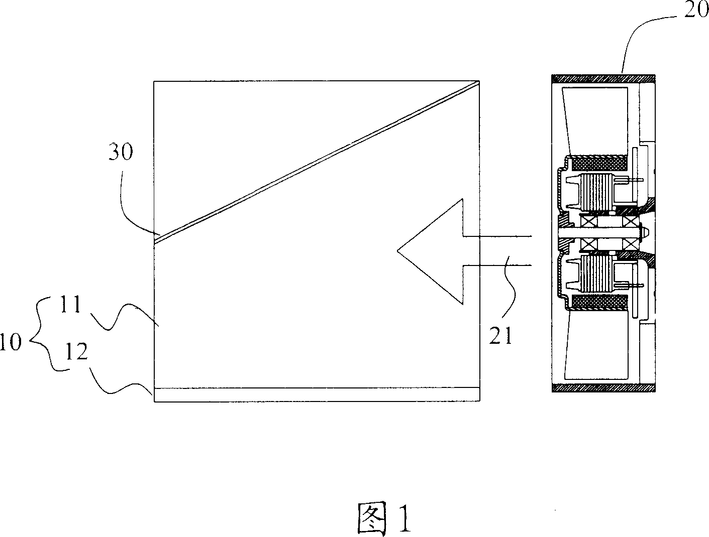
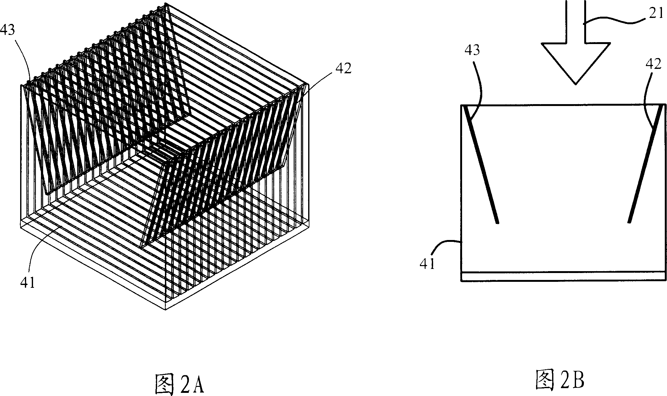
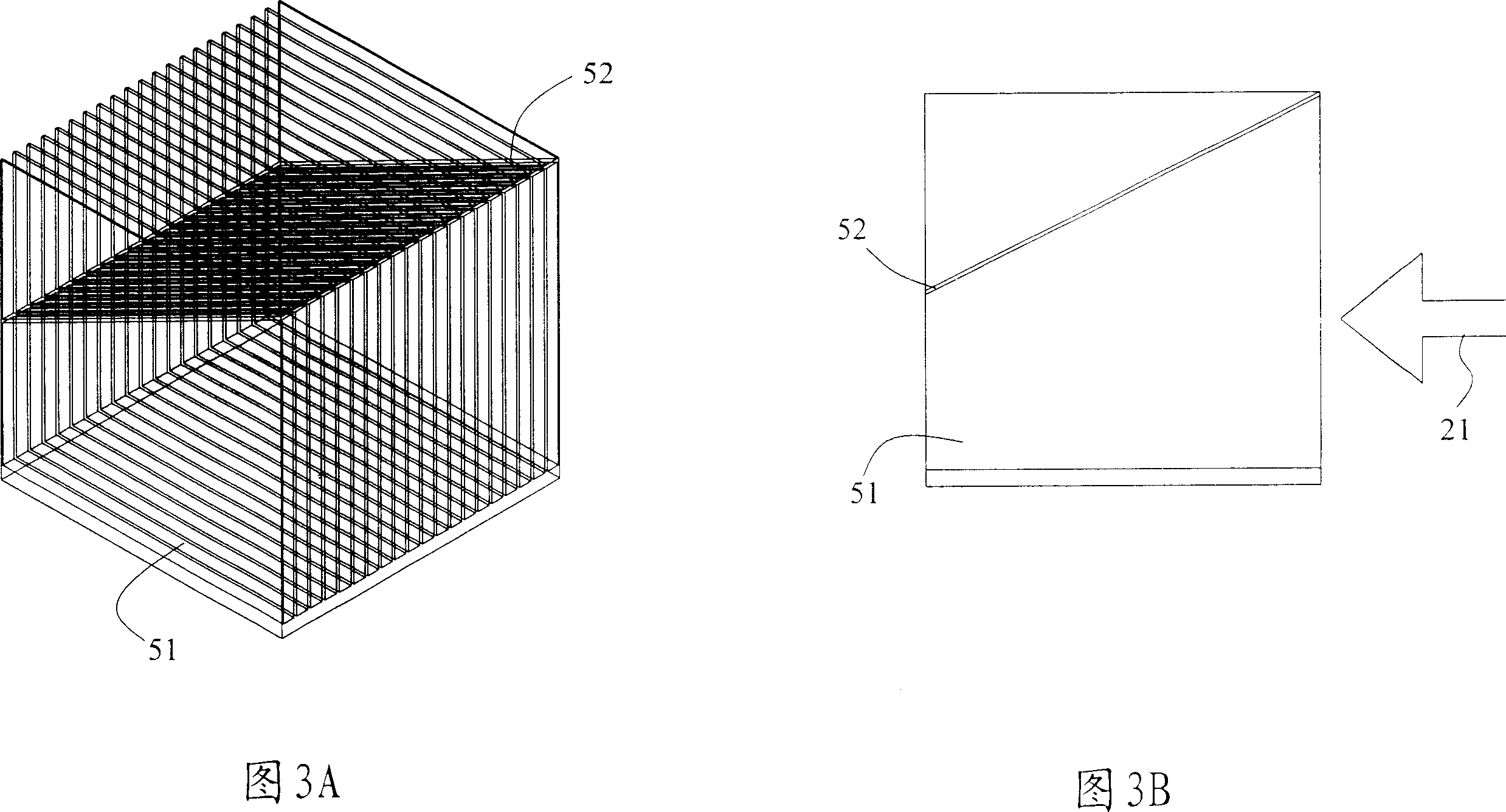
[0034] In order to further explain the technical means and effects that the present invention adopts to achieve the intended purpose of the invention, the specific implementation, structure and characteristics of the radiator with inclined fins proposed according to the present invention will be described below in conjunction with the accompanying drawings and preferred embodiments. And its effect, detailed description is as follows.

[0035] The radiator with inclined fins disclosed according to the embodiment of the present invention is aimed at the problem of insufficient heat dissipation caused by the difficulty of dissipating the hot air at the end of the flow field of the traditional radiator due to the weakening of the wind speed, and improves the radiator. The flow field configuration can also be applied to the existing radiator types, and it can be improved by directly adding inclined fins, which has a wide range of applications. In order to form a flow field, the rad...


PUM


Abstract

This invention relates to a radiator with slant fins, which adds slant fins on the fins of a traditional radiator to alter the passed section area on the flow channel direction formed by fan blowing to increase its flow rate to avoid stacking of hot air far from the fan.

Description

technical field [0001] The invention relates to a heat sink applied to electronic devices, in particular to a heat sink with inclined fins capable of changing air flow velocity. Background technique [0002] With the rapid development of science and technology, the computing speed of chips such as the central processing unit is getting higher and higher, and the heat generated thereupon makes the temperature rise even more. The graphics chip on the display card is also getting faster and faster in computing speed, so it is necessary to install a radiator to cool it down to the normal operating temperature range. [0003] As far as the chip set of the above-mentioned computer system is concerned, it can be roughly divided into chips on the motherboard, such as the central processing unit, south bridge, and north bridge chips, and chips on the interface card, such as the graphics chip on the display card. The increasing rate of chip computing speed is getting bigger and bigge...

Claims


Application Information

Patent Timeline
Patent Type & Authority Applications(China)
IPC IPC(8): H01L23/367F28D1/04F28F1/34H05K7/20
Inventor 张瑚松
Owner ASUSTEK COMPUTER INC
Learn More