Photoconductive coating film of diffraction grating and manufacture method thereof

A technology of diffraction grating and manufacturing method, which is applied in the direction of light guide, optical waveguide coupling, optics, etc., can solve the problems of limited range of outgoing light intensity and low utilization rate of light energy, and improve the uniformity of light guide, improve the uniformity and Field of view, easily embossed and reproduced effects

Inactive Publication Date: 2007-08-15
SUZHOU UNIV +1
View PDF3 Cites 26 Cited by
  • Summary
  • Abstract
  • Description
  • Claims
  • Application Information

AI Technical Summary

Problems solved by technology

U.S. Patent No. 7,058,056 discloses a light guide plate with a diffraction grating. A diffraction grating with a grating constant of 2 μm is used as the light guide unit on the bottom surface of the light guide plate. The effect of uniform emission of the light source is achieved by changing the area of ​​the diffraction grating unit. However, this The range of output light intensity that can be adjusted in this way is very limited, the utilization rate of light energy is low, and prism sheet is still needed

Method used


Image

  • Photoconductive coating film of diffraction grating and manufacture method thereof
  • Photoconductive coating film of diffraction grating and manufacture method thereof
  • Photoconductive coating film of diffraction grating and manufacture method thereof

Examples


Embodiment 1

[0040] Embodiment 1: Referring to accompanying drawings 1 to 5, a method for making a light guide pattern on a film by using a digital interference lithography system and a molding system to prepare a diffraction grating light guide film includes the following steps:

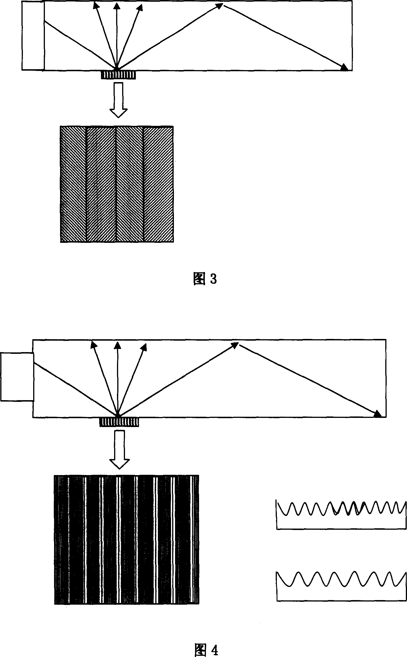
[0041] (1) According to the uniformity requirements of the light guide, the diffraction structure distribution of the light guide pattern is designed, and the direction of the light guide is determined by the grating equation and the law of refraction; The intensity is determined by the orientation and area ratio of the diffraction grating in the light guide pattern;

[0042] The plane formed by the diffracted light and the incident light is always perpendicular to the grating lines. Therefore, rotating the orientation of the grating can change the spatial azimuth of the diffracted light. perspective. See accompanying drawings 1a and 1b.

[0043] The higher the spatial frequency of the grating, the larger the ...

Embodiment 2

[0050] Embodiment 2: A method for improving the uniformity of a diffraction grating light guide film, comprising the following steps:

[0051] (1) According to the uniformity requirements of the light guide, the distribution of the diffraction grating structure of the light guide pattern is designed, and the direction of the light guide is determined by the grating equation and the law of refraction; The intensity is determined by the orientation of the diffraction grating in the light guide pattern and the proportion of the area occupied by different structured gratings; in order to obtain the uniformity of light guide, a digital micro-mirrordevice (DMD) is used as the input method to combine the pixels of the diffraction grating , the light guide patterns of different light guide structures are obtained,

[0052] (2) Arranging the light guide patterns generated in step (1) into different sequences according to the pixel structure distribution, corresponding to different diff...


PUM

PropertyMeasurementUnit
depthaaaaaaaaaa
refractive indexaaaaaaaaaa

Abstract

This invention discloses one infraction grating guide conductive film, wherein, one side of surface is set with grating pixel units and the invention is characterized by the following: the grating pixel unit is composed of sub pixel structure with each one determined by infraction grating, space frequency, tank depth guide light direction and intensity. The process method comprises the following steps: a, designing guide pattern infraction structure distribution; b, distributing the pixel structure on guide pattern with each unit formed with sub pixel element and each one infraction grating taking, space frequency alternated; c, etching; d, through casting to process metal nickel board for printing on coat layer of PET or PC film.

Description

technical field [0001] The invention relates to a light guide film used in a backlight module and a manufacturing method thereof, in particular to a light guide film with a diffraction grating. Background technique [0002] The backlight module is a necessary device in LCD monitors, liquid crystal display modules and keyboard lighting used in mobile phones, PDAs, digital cameras, etc. Its market is globalized. With the rapid development of the display industry, lightweight, ultra-thin Small and low-energy backlight modules have become a research and development trend in this field. The light guide plate is an important optical component in the backlight module. Its structure and performance directly affect the quality of the backlight. Therefore, how to design and manufacture high-performance Light guide plate is the focus of current research at home and abroad. [0003] A main type of backlight is the side-light backlight module, which is composed of a light source, a ligh...

Claims


Application Information

Patent Timeline
Patent Type & Authority Applications(China)
IPC IPC(8): G02B6/00G02B6/124G02B6/34G02B1/10G02F1/13357G02F1/1335
Inventor 陈林森周小红叶燕浦东林陆亚聪魏国军解剑锋汪振华沈雁
Owner SUZHOU UNIV
Why Eureka
Try Eureka