
Method and system for transmitting monitoring data of communication base station

A technology for monitoring data and communication base stations. It is applied in wireless communication, network data management, electrical components, etc. It can solve the problems of reduced management efficiency, powerlessness of base stations, and difficulty in maintenance, so as to speed up upload speed, improve detection speed, and reduce data volume. Effect

Inactive Publication Date: 2012-07-18
姜宏伟
View PDF0 Cites 0 Cited by
  • Summary
  • Abstract
  • Description
  • Claims
  • Application Information

AI Technical Summary

Problems solved by technology

[0008] 1. The monitoring system adopts an independent network of optical cables, which has a large investment cost, occupies many network channel resources and equipment, and has many optical cable transmission links, high operating costs, high dependence on network transmission links, and difficult maintenance, which directly affects the monitoring of communication base stations system availability
[0009] 2. The amount of base station monitoring information data is very large. To realize the storage and processing of system data (including various reports), alarm query analysis and statistics, etc., the monitoring center must use large databases and storage devices, which will affect the management and maintenance of the monitoring system. s efficiency
[0010] 3. The communication power system of the base station and various environmental variables generate alarms. When an alarm is sent to the monitoring center, the maintenance personnel cannot be notified directly. Moreover, it is easy to delay the repair time, affect the realization of the rapid response requirements of monitoring system management and maintenance, and even lead to major communication interruption accidents
[0011] 4. For the network base station monitoring system that relies on optical cable transmission, due to the complexity of the optical cable networking method, once the loop is completed, it is necessary to make very difficult adjustments to the original optical path when adding a new base station monitoring point. The base station can't even do anything

Method used


Image

  • Method and system for transmitting monitoring data of communication base station
  • Method and system for transmitting monitoring data of communication base station
  • Method and system for transmitting monitoring data of communication base station

Examples


Embodiment 2

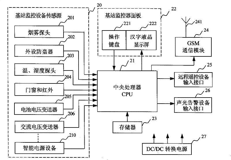
[0144] In Example 2, the intelligent switching power supply is equipped with ECO intelligent switching power supply, and the monitoring data of the base station monitor is divided into 4 pieces:

[0145] a. Monitor self-test value alarm data block: analog quantity, switch value and field strength data of the monitor self-test alarm state;

[0146] b. Timing data block of monitor self-test value: analog quantity, switch quantity, field strength data and parameter setting quantity of monitor self-test alarm state;

[0147] c. Intelligent switch power switchboard alarm data block: the analog and switch values ​​of the system;

[0148] d. Timing data block of switchboard of intelligent switching power supply: analog quantity, switch quantity and parameter setting quantity of the system.

[0149] The short message monitoring system only needs a very low monitoring cost to achieve high reliability, low code error, and long-distance high-grade monitoring level. By applying the metho...


PUM


Abstract

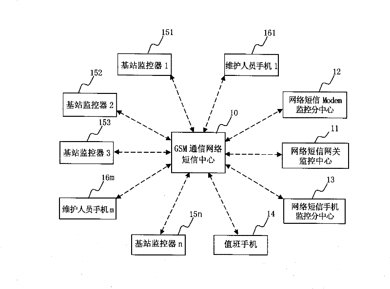
The invention relates to one digital mobile communication technique suitable for one transmission base station monitor method and system based on wireless mobile terminal, which uses GSM communication network short message channel to sort monitor data and to transmit on focus degree, wherein, the alarm information and inquire information send by real time and the operation information without alarm sends method and process technique to form alarm guide base station monitor system by network monitor center, base station and other human cell phone network.

Description

[0001] Field [0002] The patent of the present invention relates to digital mobile communication technology, and is especially suitable for a method and system for transmitting communication base station monitoring data based on a short message channel of a wireless mobile communication network. Background technique [0003] The GSM wireless mobile communication network uses tens of thousands of communication base stations as the supporting nodes for its network operation. With the expansion of GSM network service business and coverage area, the number of communication base stations is increasing day by day, and the maintenance work of base stations is becoming increasingly heavy. . GSM network service quality depends to a large extent on its ability to monitor and maintain communication base stations. To this end, the GSM network has established a set of communication base station monitoring system, through which the system operates continuously around the clock, so that ea...

Claims


Application Information

Patent Timeline
Patent Type & Authority Patents(China)
IPC IPC(8): H04W8/08H04W24/04
Inventor 姜宏伟
Owner 姜宏伟
Learn More