Method for detecting induction coil velocimeter
A detection method and sensing coil technology, applied in the field of detection, can solve the problems of low accuracy, lack of safety, driving, etc., and achieve the effects of high accuracy, data reproduction, and strong safety
- Summary
- Abstract
- Description
- Claims
- Application Information
AI Technical Summary
Problems solved by technology
Method used
Image

Examples
Embodiment 1
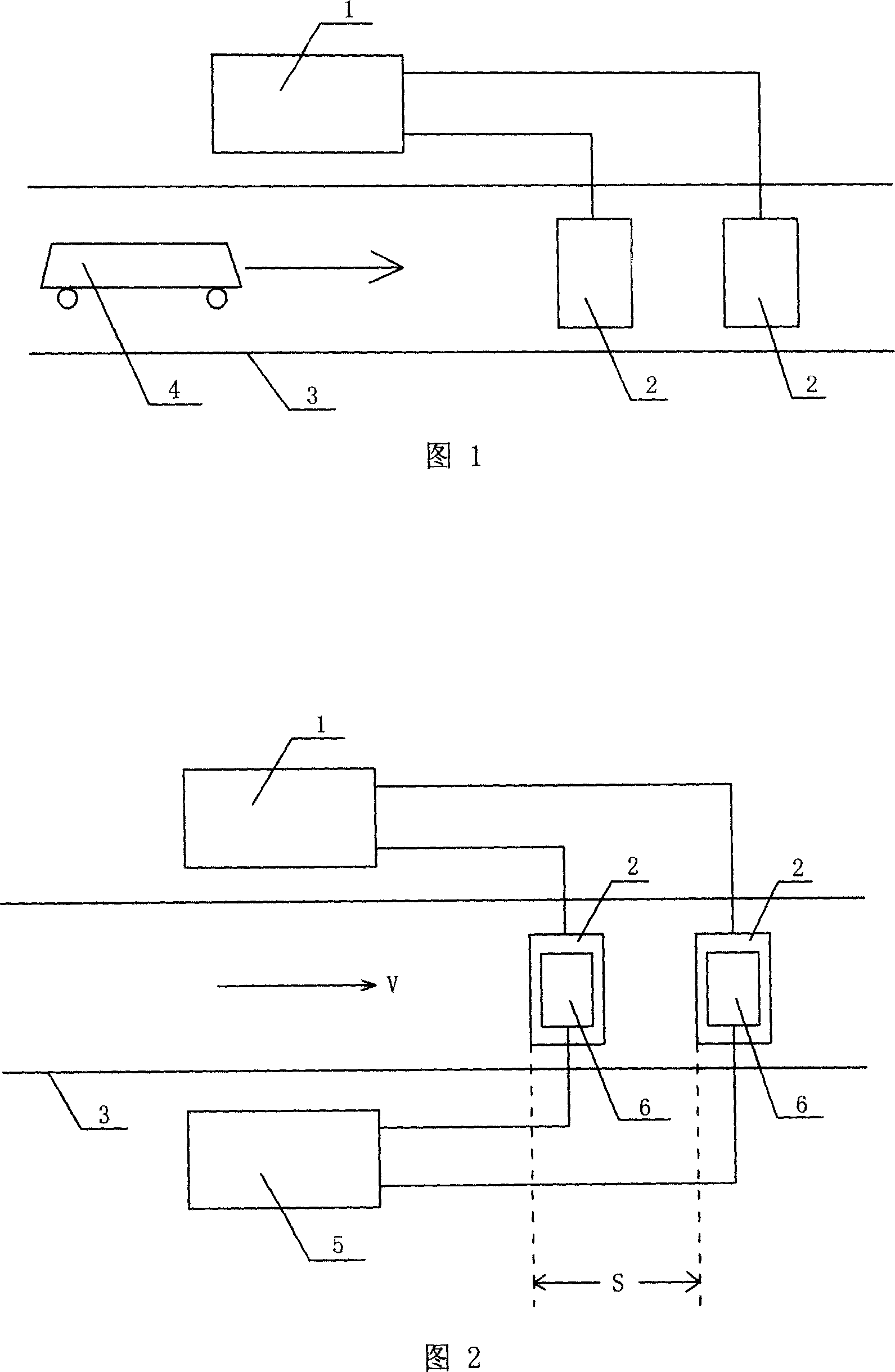
[0032] This embodiment detects the ground induction coil speedometer, installs the ground induction coil type speedometer on a certain road, buries the two ground induction coils of the ground induction coil type speedometer underground, and places each above the two ground induction coils. Put an interference coil, the interference coil is connected with the verification device of the ground induction coil speedometer, and the verification device of the ground induction coil type speedometer applies two interference signals to the two interference coils respectively, and the time interval between the two interference signals is T is 187.2ms , the distance S between the two ground induction coils is 5.2m, the speed detected by the ground induction coil speedometer is 100.1km / h, and the simulated speed V=S / T=5.2(m)÷187(ms)= 100 (km / h), the simulated speed V is compared with the speed detected by the ground induction coil speedometer, and the speed measurement error of the ground...
Embodiment 2
[0034] This embodiment detects the ground induction coil speedometer, installs the ground induction coil type speedometer on a certain road, buries the two ground induction coils of the ground induction coil type speedometer underground, and places each above the two ground induction coils. Put an interference coil, the interference coil is connected with the verification device of the ground induction coil speedometer, and the verification device of the ground induction coil type speedometer applies two interference signals to the two interference coils respectively, and the time interval between the two interference signals is T is 234.0ms , the distance S between the two ground induction coils is 5.2m, the speed detected by the ground induction coil speedometer is 80.2km / h, and the simulated speed V=S / T=5.2(m)÷234.0(ms)= 80 (km / h), the simulated speed V is compared with the speed detected by the ground induction coil speedometer, and the speed measurement error of the ground...
Embodiment 3
[0036]This embodiment detects the ground induction coil speedometer, installs the ground induction coil type speedometer on a certain road, buries the two ground induction coils of the ground induction coil type speedometer underground, and places each above the two ground induction coils. Put an interference coil, the interference coil is connected with the verification device of the ground induction coil speedometer, and the verification device of the ground induction coil type speedometer applies two interference signals to the two interference coils respectively, and the time interval between the two interference signals is T is 312.0ms , the distance S between the two ground induction coils is 5.2m, the speed detected by the ground induction coil speedometer is 60.0km / h, and the simulated speed V=S / T=5.2(m)÷312.0(ms)= 60 (km / h), the simulated speed V is compared with the speed detected by the ground induction coil speedometer, and the speed measurement error of the ground ...
PUM
 Abstract
Description
Claims
Application Information
 - R&D
- Intellectual Property
- Life Sciences
- Materials
- Tech Scout
- Unparalleled Data Quality
- Higher Quality Content
- 60% Fewer Hallucinations
Browse by: Latest US Patents, China's latest patents, Technical Efficacy Thesaurus, Application Domain, Technology Topic, Popular Technical Reports.
© 2025 PatSnap. All rights reserved.Legal|Privacy policy|Modern Slavery Act Transparency Statement|Sitemap|About US| Contact US: help@patsnap.com