
Automatic temperature control apparatus of mould

An automatic control device and mold temperature technology, which is applied in the direction of auxiliary non-electric temperature control and electric temperature control, etc., can solve the problems of equipment aging and damage, waste of production time, and inconsistent product accuracy, so as to avoid mold temperature. Overshoot, easy management, and stable production quality

Inactive Publication Date: 2007-08-08
李小卿
View PDF1 Cites 20 Cited by
  • Summary
  • Abstract
  • Description
  • Claims
  • Application Information

AI Technical Summary

Problems solved by technology

Intellectual Property Literature Publishing House disclosed a mold temperature control system with an application number of 02124412.X on China Intellectual Property Network on August 13, 2003. Warm water or cold water is the technical solution to control the working temperature of the mold, and the innovation of this patented technology only solves the technical problem of back pressure in the system pipeline, but there are still many deficiencies: (1) It cannot automatically control the mold temperature, only When the mold is cold, the mold is heated, and when the mold is hot, it is cooled, which can only be operated repeatedly, wasting electric energy, and the equipment becomes old and damaged quickly; (2) The cushioning problem cannot be solved when the mold is overheated or overcooled, and the mold temperature cannot be controlled at the set value Within the scope of the product, the precision of the product produced within 24 hours is inconsistent, and the product quality is unstable. Therefore, it is necessary to arrange special personnel to supervise and inspect, which is a waste of manpower; (3) when the mold is inspected, cleaned and repaired midway, the mold temperature changes. It is necessary to reheat the mold to the working temperature of the mold, wasting production time

Method used


Image

  • Automatic temperature control apparatus of mould
  • Automatic temperature control apparatus of mould
  • Automatic temperature control apparatus of mould

Examples


Embodiment Construction

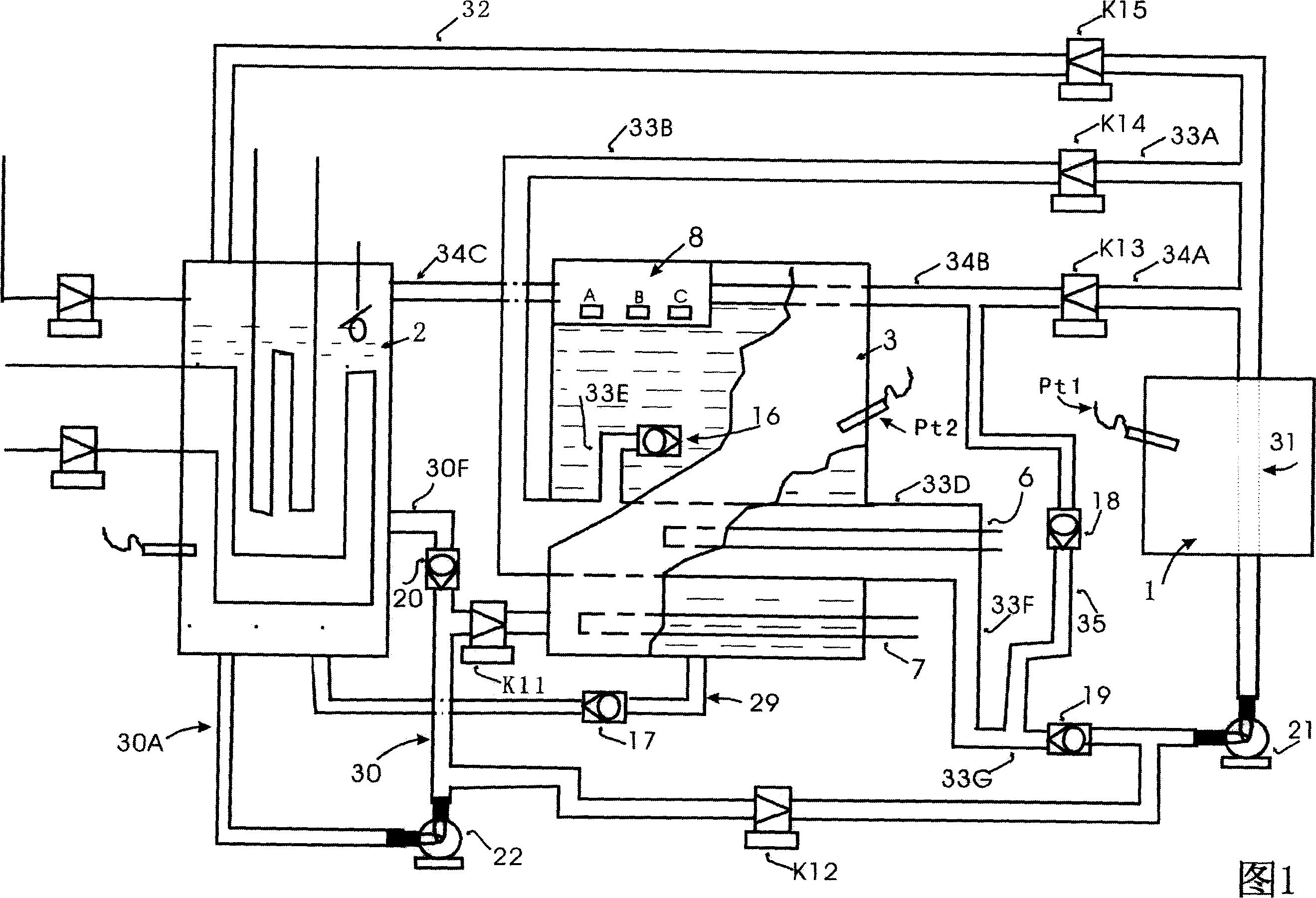
[0017] As shown in Figure 1, the present embodiment comprises heating circulation system, cooling circulation system and operation working water tank circulation system, wherein:

[0018] (1) Heating cycle system: as shown in Figure 5 (the route indicated by the arrow), it is mainly composed of the heating pipe 6, the heat booster pump 21 and the solenoid valve K14 arranged in the pipeline, and the output end of the heat booster pump 21 , mold heating or cooling channel 31, electromagnetic valve K14, pipelines (33B, 33D, 33F, 33G), and heat booster pump 21 input ends are connected in sequence to form a heating cycle pipeline, wherein the pipeline section 33D of the heating pipe 6 is worn By running the working water tank 3, when the heating tube is heated, the heat diffused from the pipeline section 33D is directly transferred to the water tank, so that the heat energy will not be wasted during heating; at the same time, when the mold is closed and the cold compensation operati...


PUM


Abstract

The invention relates to the mold temperature control system, particularly a mold temperature automatic control device, which includes the heating circulation system, the cooling circulation system, and the operation working water tank circulation system, the output of the water tank temperature control device in the operation working water tank circulation system respectively connecting with the water tank cold compensation conditioning system and heating pipe control terminal, and the input connecting with the output of the temperature sensor in the water tank, the control end connecting with the output of the temperature sensor in the mold. Its purpose is to design the mold temperature automatic control device, which can effectively control the mold temperature, and avoid the mold temperature overshoot when the mold in the heating or cooling. Compared with the existing technology, it has the advantages of automatic mold temperature control, accurate control range, saving working, saving time, saving material, and saving energy.

Description

technical field [0001] The invention relates to a mold temperature control system, in particular to an automatic mold temperature control device. Background technique [0002] When molding plastic products, in order to ensure the injection molding accuracy of the product and prevent defective products, it is usually necessary to control the working temperature of the mold within a certain range. The Intellectual Property Literature Publishing House disclosed a mold temperature control system with an application number of 02124412.X on the China Intellectual Property Network on August 13, 2003. Warm water or cold water is used to adjust and control the technical solution of mold working temperature, and this patented technological innovation only solves the technical problem of back pressure in the system pipeline, but there are still many deficiencies: (1) The mold temperature cannot be controlled automatically, only The mold is heated when the mold is cold, and the mold is...

Claims


Application Information

Patent Timeline
Patent Type & Authority Applications(China)
IPC IPC(8): G05D23/185G05D23/19B29C45/78B29C45/58B29C33/02
Inventor 李小卿
Owner 李小卿
Learn More