
Hybrid power supply unit

一种混合电源、电池组的技术,应用在电路装置、电池电路装置、电池等方向

Inactive Publication Date: 2007-07-25
PANASONIC CORP
View PDF4 Cites 7 Cited by
  • Summary
  • Abstract
  • Description
  • Claims
  • Application Information

AI Technical Summary

Problems solved by technology

[0006] However, the conventional hybrid power supply devices proposed in Patent Documents 1 to 4 use different kinds of power supplies and different kinds of components in combination. Therefore, in order to optimize the driving of these different kinds of power supplies and different kinds of components, a current control circuit, a voltage boosting mechanism, Complex control systems such as residual capacity detection mechanism, charging control mechanism, and bidirectional DC / DC converter

Method used


Image

  • Hybrid power supply unit
  • Hybrid power supply unit

Examples


Embodiment approach 1

[0016] FIG. 1 is a schematic diagram showing an example of a hybrid power supply device 3 according to this embodiment. In the hybrid power supply device 3 of this Fig. 1, the high-capacity nonaqueous electrolyte battery pack 1 and the high power type nonaqueous electrolyte battery pack 2 are connected in parallel, and each battery pack has a single cell, that is, a nonaqueous electrolyte battery 1a, or 2a.

[0017] The present embodiment is characterized in that the nonaqueous electrolyte battery 1a constituting the high-capacity nonaqueous electrolyte battery pack 1 has different discharge characteristics than the nonaqueous electrolyte battery 2a constituting the high power nonaqueous electrolyte battery pack 2 . That is, the hybrid power supply device 3 of the present invention is designed as follows: for the discharge capacity of 0.2C of low load, the nonaqueous electrolyte battery 1a is greater than the nonaqueous electrolyte battery 2a; and for the discharge capacity of...

Embodiment approach 2

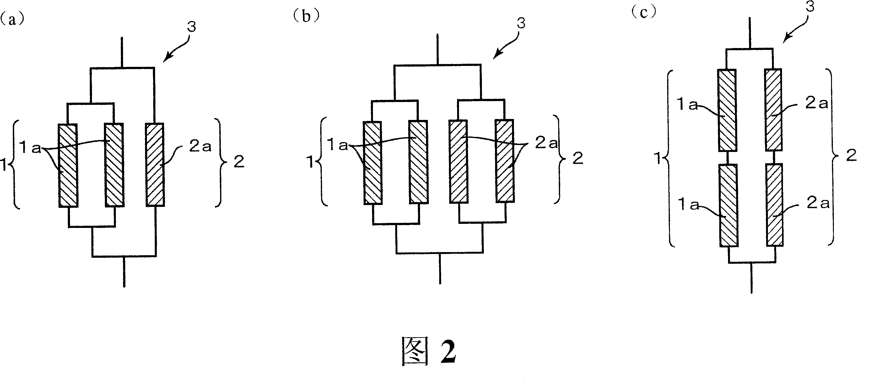
[0034] In the hybrid power supply device of this embodiment, at least one of the high-capacity non-aqueous electrolyte battery pack and the high-power non-aqueous electrolyte battery pack may have a structure including a plurality of non-aqueous electrolyte batteries. 2( a ) to ( c ) are schematic diagrams showing an example of a hybrid power supply device according to this embodiment. In addition, since the discharge characteristics and electrode structures of the non-aqueous electrolyte batteries used in this embodiment are the same as those of the non-aqueous electrolyte batteries described in Embodiment 1, description thereof will be omitted here, and only the differences will be described.

[0035] Fig. 2 (a) shows a kind of hybrid power supply device, wherein high-capacity type nonaqueous electrolyte battery pack 1 is connected in parallel with 2 nonaqueous electrolyte batteries 1a, and this high capacity type nonaqueous electrolyte battery pack 1 is connected with 1 nona...

Embodiment 1

[0067] A battery pack consisting of one lithium ion secondary battery A and one lithium ion secondary battery F was connected in parallel to fabricate a hybrid power supply device.


PUM

PropertyMeasurementUnit
current densityaaaaaaaaaa
coating massaaaaaaaaaa

Abstract

The present invention provides a composite power source device which is parallel-connected with a high-capacity non-aqueous electrolyte battery set and a high-power non-aqueous electrolyte battery set which have different discharge properties, wherein: the discharge capacity of each single battery in the high-capacity non-aqueous electrolyte battery set at 0.2C is higher than the discharge capacity of each single battery in the high-power non-aqueous electrolyte battery set at 0.2C; besides the ratio between the discharge capacity of each single battery in the high-power non-aqueous electrolyte battery set at 5C and the discharge capacity at 0.2C is higher than the ratio between the discharge capacity of each single battery in the high-capacity non-aqueous electrolyte battery set at 5C and the discharge capacity at 0.2C. Therefore, the high-capacity property of long-time continuous discharging and the high-capacity property of impulsive discharging with great current can be simultaneously satisfied without the complicated control system.

Description

technical field [0001] The present invention relates to a power supply device, which can be applied in the following fields: the field of portable products such as mobile phones and personal computers; the field of power tools such as electric tools and cleaning machines; electric vehicles, electric industrial vehicles, electric bicycles (electric motorcycles), Power fields such as electric power assist bicycles, electric vehicle chairs, electric robots, etc.; system power supply fields such as load adjustment, peak shift (peak shift), backup, etc., etc., and more specifically, it relates to high performance of the power supply device. Background technique [0002] Compared with the field of portable products such as mobile phones and personal computers, in the field of power tools such as electric tools and power fields such as electric bicycles, the load of the power supply fluctuates greatly, and it is used continuously for a long time, so high power and high power are req...

Claims


Application Information

Patent Timeline
Patent Type & Authority Applications(China)
IPC IPC(8): H01M10/42H01M10/40H01M10/00H01M10/46H01M16/00H02J7/00H01M2/10
CPCH01M10/0413H01M10/0525H01M16/00Y02T10/7011Y02E60/122H01M4/133H01M4/131Y02E60/10H01M10/4207H01M2220/20H01M2300/0037Y02T10/70
Inventor 中岛琢也木村忠雄浅野刚太
Owner PANASONIC CORP
Learn More