
Welding method of vacuum tube central fulcrum bar component

A welding method and vacuum tube technology, applied in welding equipment, metal processing equipment, manufacturing tools, etc., can solve the problems of molybdenum cap falling off and high scrap rate of central rod components, and achieve high pass rate, simple and convenient design, and good performance Effect

Inactive Publication Date: 2007-07-18
MIDEA GRP CO LTD
View PDF0 Cites 2 Cited by
  • Summary
  • Abstract
  • Description
  • Claims
  • Application Information

AI Technical Summary

Problems solved by technology

[0002] The existing vacuum tube central pole assembly is generally composed of a molybdenum rod and a molybdenum cap. The conventional welding method for the molybdenum cap and the molybdenum rod is a direct welding welding method. The disadvantage is that the molybdenum cap is prone to fall off due to poor welding. , leading to a higher scrap rate of the center strut assembly

Method used


Image

  • Welding method of vacuum tube central fulcrum bar component

Examples


Embodiment

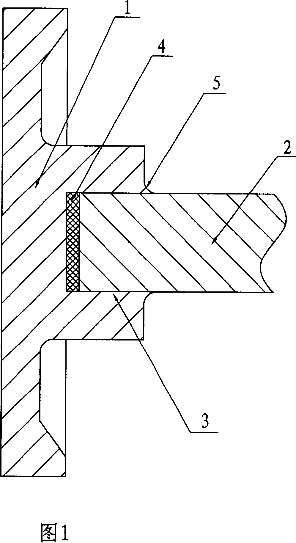
[0013] The welding method of the central rod assembly of the vacuum tube of the present invention comprises the following steps:

[0014] 1) Set up a counterbore 3 on the molybdenum cap 1;

[0015] 2) Add silicon molybdenum solder sheet 4 in the counterbore 3;

[0016] 3) Insert the molybdenum rod 2 into the counterbore 3;

[0017] 4) Weld the molybdenum rod 2 and the molybdenum cap 1 at the counterbore 3 by high-frequency welding

[0018] 5) The molybdenum cap and the molybdenum rod are welded by resistance welding at the mouth 5 of the molybdenum cap.


PUM


Abstract

The present invention relates to a welding method of vacuum-tube fulcrum bar component. Said welding method includes the following steps: 1), on the molybdenum cap cutting a sink hole; (2), adding silicon-molybdenum welding flux piece into the sink hole; 3), inserting molybdenum bar into the sink hole; 4), in the sink hole adopting high-frequency welding method to weld molybdenum bar and molybdenum cap; and 5), in molybdenum cap opening adopting resistance welding to make molybdenum cap and molybdenum bar be fusion-welded together.

Description

Technical field: [0001] The invention relates to a welding method for a vacuum tube center support rod assembly, which belongs to the modification technology of the welding method for the vacuum tube center support rod assembly. Background technique: [0002] The existing vacuum tube central pole assembly is generally composed of a molybdenum rod and a molybdenum cap. The conventional welding method for the molybdenum cap and the molybdenum rod is a direct welding welding method. The disadvantage is that the molybdenum cap is prone to fall off due to poor welding. , leading to a higher scrap rate of the central strut assembly. Invention content: [0003] The object of the present invention is to overcome the above disadvantages and provide a simple and convenient welding method for vacuum tube central rod assembly with high welding success rate and good performance. [0004] The welding method of the central rod assembly of the vacuum tube of the present invention compris...

Claims


Application Information

Patent Timeline
Patent Type & Authority Applications(China)
IPC IPC(8): B23K28/02
Inventor 周汉勇石志博
Owner MIDEA GRP CO LTD
Learn More