Electric oven

A technology for electric ovens and box bodies, applied in the field of electric ovens, which can solve the problems of insufficient comprehensiveness, large manual dependence, no permission to leave or desertion, etc., and achieve the effects of ensuring safe use, saving packing space, and increasing the use volume

Inactive Publication Date: 2010-02-24
施军达
View PDF10 Cites 0 Cited by
  • Summary
  • Abstract
  • Description
  • Claims
  • Application Information

AI Technical Summary

Problems solved by technology

[0002] With the improvement of people's living conditions and the diversification of food demand, how to use a kind of equipment to realize the fast cooking of food has become a problem that people have to think about. Traditional food baking mostly uses simpler utensils, such as The raw food is directly placed on the electric heating plate, and the baking of the food is controlled according to people's own actual experience. Generally, the operator is not allowed to leave or desert during the baking process, and the effect of the baked food cannot be controlled by itself. The dependency is large, so this class is a relatively simple way
[0003] There is also a kind of equipment that can be automatically controlled to realize food baking in the society at present, such as the Chinese utility model patent "a new type of electric oven" (announcement number is CN2935815Y) that is ZL200620016833.8 as the patent number is exactly this type of design; the electric oven includes 2- 3 lower electric heating tubes installed in parallel, reflectors are arranged between adjacent lower electric heating tubes, the reflectors have two adjacent reflective surfaces, and each reflective surface obliquely faces the electric heating tubes on each side and the grid above it. Although this design improves the convenience of operation to a certain extent, it cannot effectively classify and control the specific food that is controlled. Its use method is single and not comprehensive enough, including temperature setting and corresponding time automatic control, etc.

Method used


Image

  • Electric oven
  • Electric oven
  • Electric oven

Examples


Embodiment Construction

[0022] The present invention will be further described in detail below in conjunction with the accompanying drawings and embodiments.

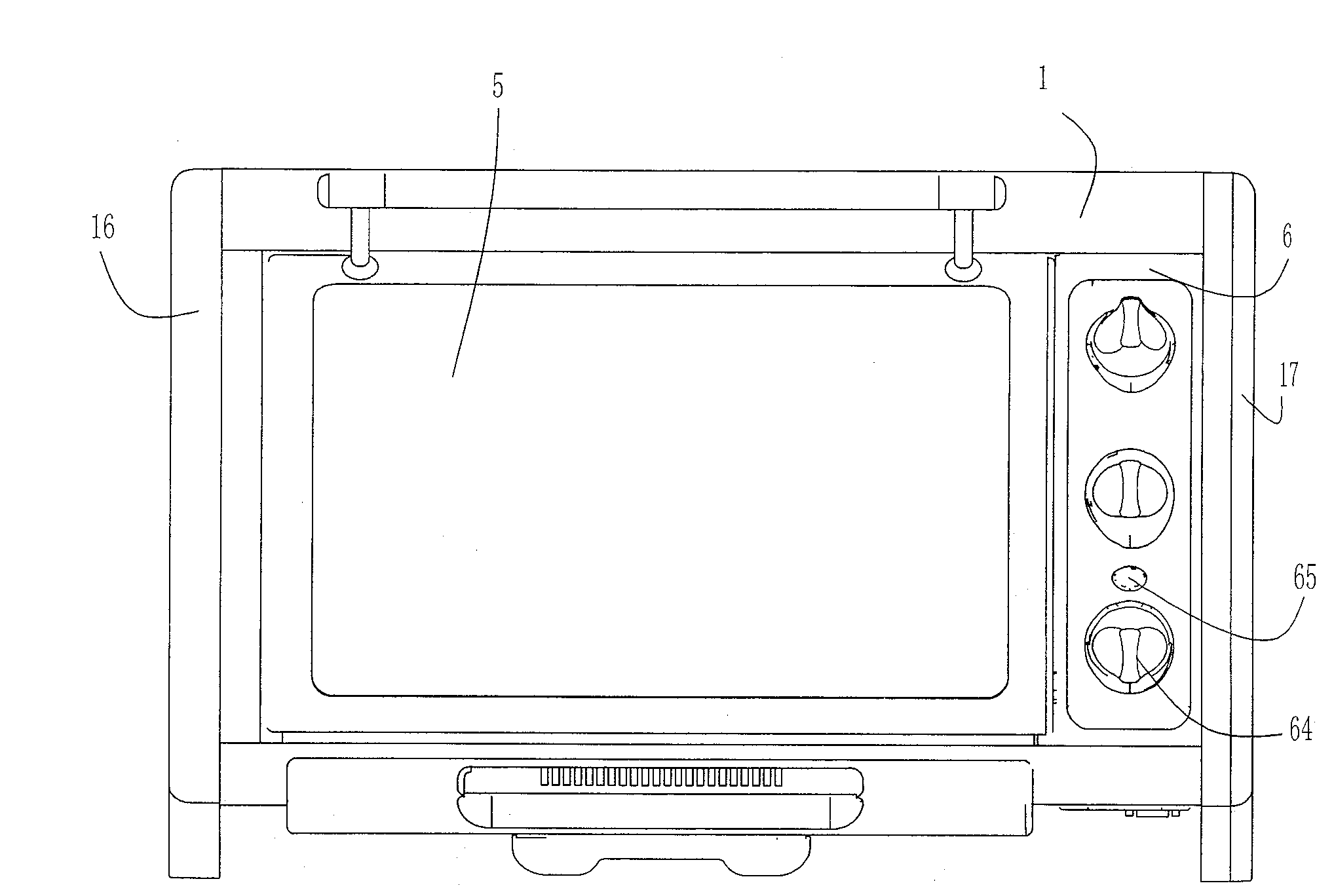
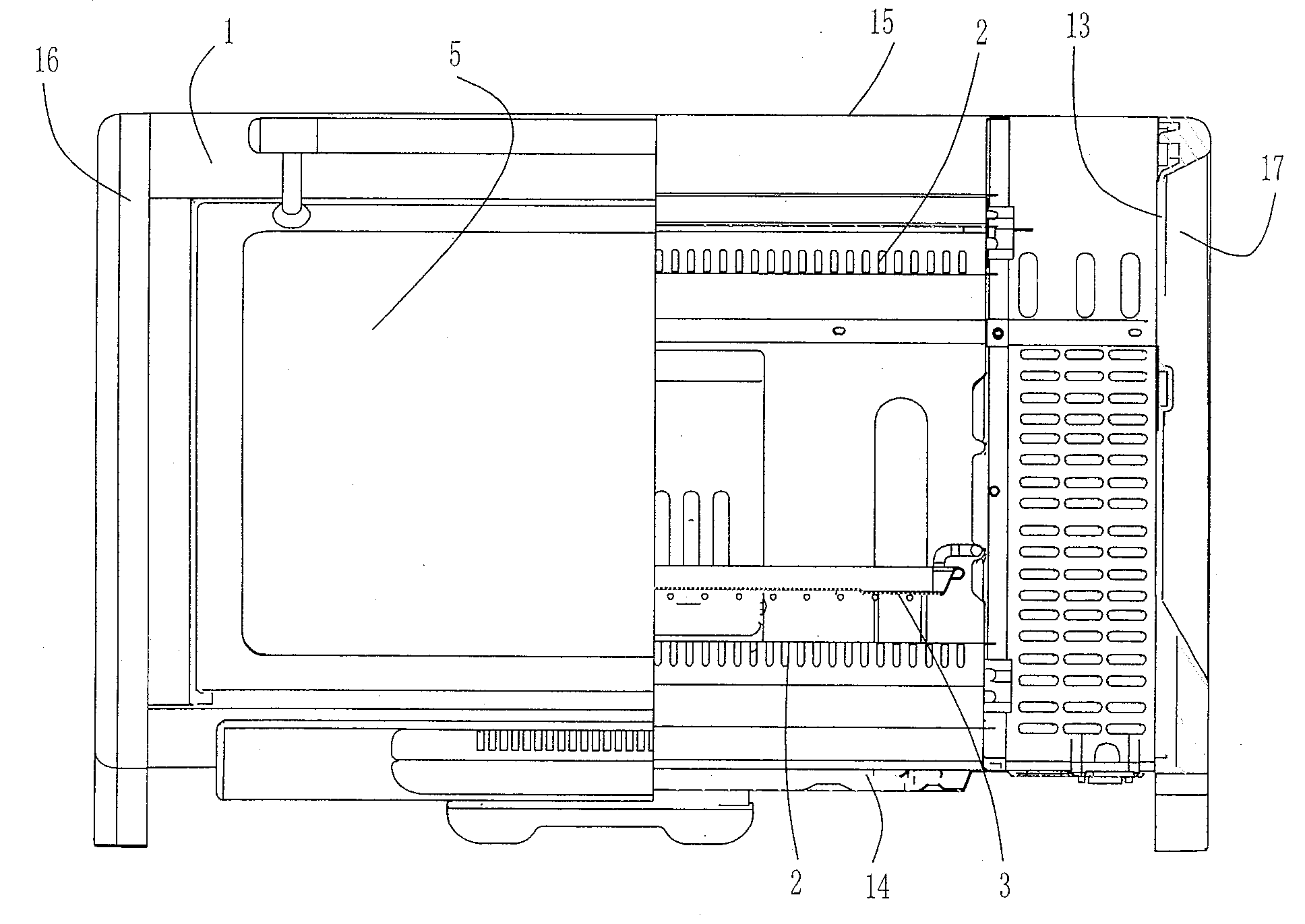
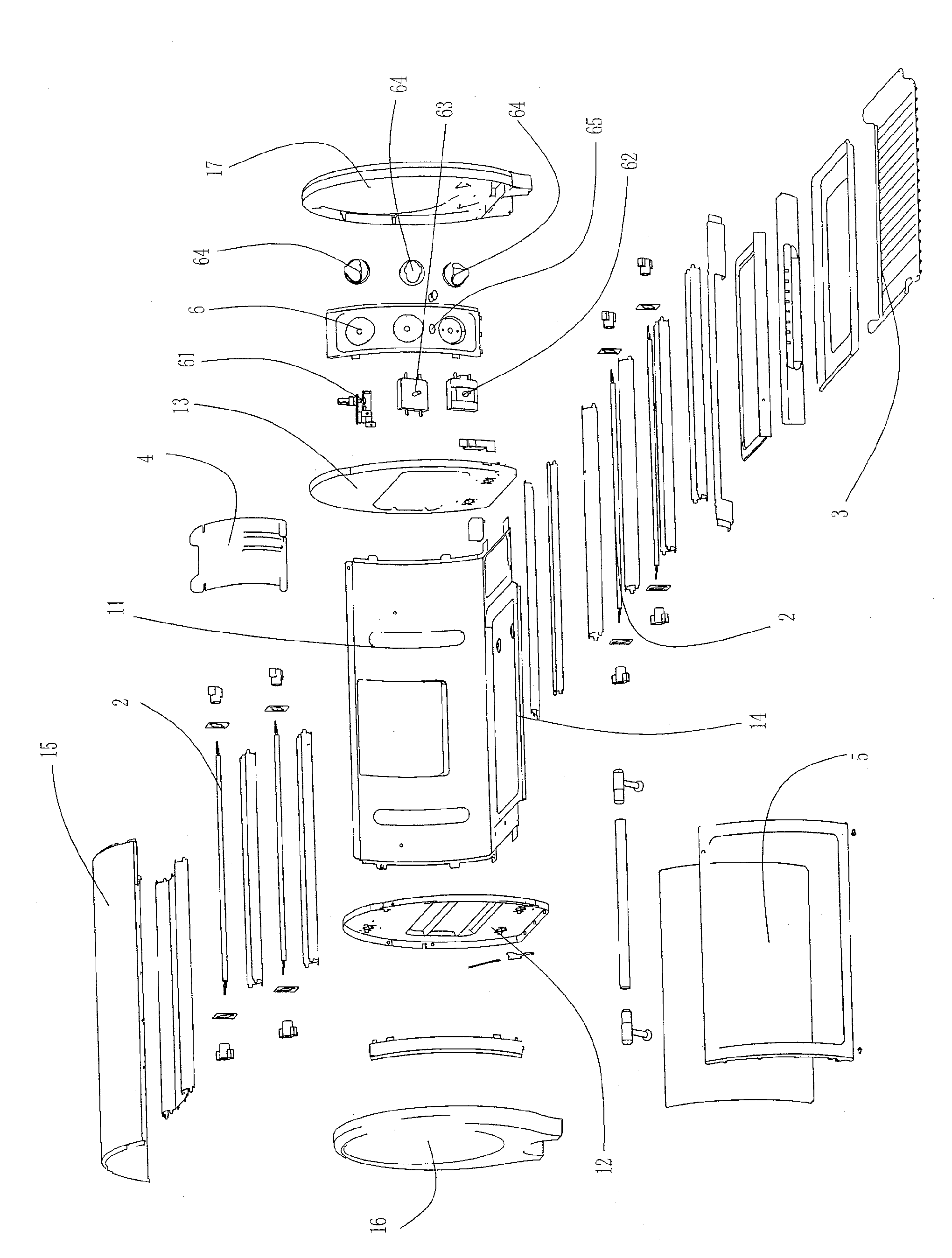
[0023] Such as Figure 1 to Figure 5 The embodiment shown, the figure number description: box body 1, rear shell 11, left fixed side plate 12, right fixed side plate 13, bottom shell 14, top shell 15, left side cover 16, right side cover 17, electric heating tube 2. Grill 3, top wall panel assembly 4, tempered glass door 5, panel 6, adjustable thermostat 61, timer 62, gear switch 63, knob 64, working indicator light 65.

[0024] In an embodiment of the present invention, an electric oven includes a box body 1, which is equipped with two sets of electric heating tubes 2 arranged one above the other and a grill 3 arranged in the middle cavity; the back of the box body 1 is equipped with Rear shell 11, the outer surface of the rear shell 11 is movably connected with a top wall panel assembly 4; the front of the box body 1 is turned down and hing...


PUM


Abstract

The invention discloses an electronic oven which includes an oven body. The oven body is equipped with two groups of electrical heating tubes which are arranged upper and lower and a griddle which isarranged in a middle inner cavity. The back of the oven body is equipped with a back casing. The outer surface of the back casing is movably connected with a top wallboard component. The front face ofthe oven body is hinged with a transparent toughened glass gate in a way of turning downward. A panel which is arranged to be parallel with the toughened glass gate is fixed on the front face of theoven body. Black high temperature resistance oil is sprayed on the inner cavity wall of the oven body to further guarantee the baking temperature in the cavity. The baking condition of foods in the oven body can be clearly observed from the high temperature resistance transparent toughened glass gate. The whole structure is changed from the traditional square shape into the cylindrical shape. Withliberal appearance, the actual using volume is increased. A movable top wallboard is added on the back casing. When the movable top wallboard component is folded to be fixed, the oven space is saved.When the movable top wallboard component is put down, the electric oven does not touch wall corners, which guarantees the using safety.

Description

technical field [0001] The invention relates to the technical field of food processing appliances, in particular to an electric oven, which uses the radiant heat emitted by the upper and lower heating tubes to bake food, and is suitable for making roasted beef cakes, baked bread, roasted chicken, Roast duck, pastries, etc. Background technique [0002] With the improvement of people's living conditions and the diversification of food demand, how to use a kind of equipment to realize the fast cooking of food has become a problem that people have to think about. Traditional food baking mostly uses simpler utensils, such as The raw food is directly placed on the electric heating plate, and the baking of the food is controlled according to people's own actual experience. Generally, the operator is not allowed to leave or desert during the baking process, and the effect of the baked food cannot be controlled by itself. The dependency is large, so this class is a relatively simpl...

Claims


Application Information

Patent Timeline
Patent Type & Authority Patents(China)
IPC IPC(8): A47J37/06
Inventor 施军达
Owner 施军达
Why Eureka
Try Eureka