Electric spanners

A motor-driven, pawl technology, applied in the field of electric wrench, can solve the problems of non-adjustable impact torque, no overload protection, low impact torque, etc., to achieve the effect of improved impact torque, reliable action, and large impact torque

Inactive Publication Date: 2009-11-11
戴冬军
View PDF10 Cites 0 Cited by
  • Summary
  • Abstract
  • Description
  • Claims
  • Application Information

AI Technical Summary

Problems solved by technology

But the electric wrench of this kind of structure still has the unsatisfactory place, this electric wrench drives ratchet 8 ' through two cylindrical pins 6 ' that are fixed on the ratchet seat 7 ' and thereby drives ratchet seat 7 ' to complete its high-speed rotation, exists The disadvantages of low impact torque and poor reliability, and the impact torque cannot be adjusted, and there is no overload protection function

Method used


Image

  • Electric spanners
  • Electric spanners
  • Electric spanners

Examples


Embodiment Construction

[0012] The present invention will be further described in detail below in conjunction with the accompanying drawings and embodiments.

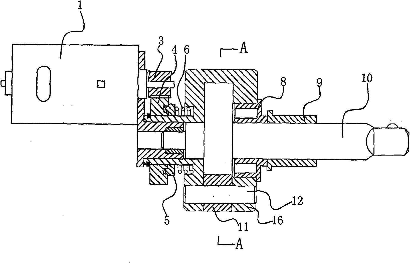
[0013] Such as figure 1 with figure 2 As shown, the electric wrench includes a motor 1, a pinion 3 driven by the motor 1, a large gear 4 meshing with the pinion 3, a clutch 5 is movably embedded in the large gear, and the clutch spring 6 is set against the Between ratchet seat 16 and clutch 5.

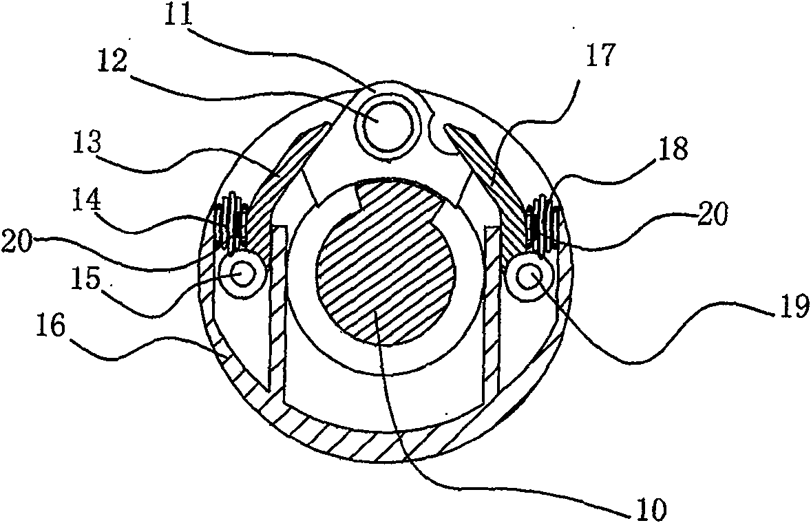
[0014] Such as figure 2 As shown, the ratchet 10 is located at the central position of the ratchet seat 16, and its two sides respectively have an inner limit plate 8 and an outer limit plate 9 on the ratchet seat 16, and the left cylindrical pin 15 and the right cylindrical pin 19 are fixed respectively. Located on both sides of the ratchet seat 16 and between the inner limit plate 8 and the outer limit plate 9, the ratchet 11 is pivotally connected to the ratchet seat 16 through a large cylindrical pin 12; the left pawl pressing plate 13 and th...


PUM


Abstract

The invention relates to an electric wrench, which includes a pinion gear driven by a motor, a large gear meshed with the pinion gear, a ratchet seat, a pawl and a ratchet wheel, and the pawl and ratchet wheel are fixed on the ratchet wheel seat, and is characterized in that: The large gear is connected to the clutch, and the clutch drives the ratchet seat to rotate through the clutch spring; two left and right pawl pressure plates are arranged on the ratchet seat and both sides of the ratchet wheel, and one end of the pawl pressure plate is fixed on both sides of the ratchet wheel. One end rests on the inclined side of the ratchet. The present invention adopts the ratchet pressing plate to replace the separation and closing of the cylindrical pin and the ratchet in the background technology so that the ratchet interval generates impact torque, improves the impact torque of the electric wrench, and improves the operation stability and reliability of the electric wrench; the large gear and The use of the clutch and the clutch spring between the ratchet seat, when the torque the ratchet bears is greater than the rated torque, the clutch spring clamped between the clutch and the large gear will generate greater compression to limit the relative movement of the clutch, thereby The output torque of the ratchet is limited within the rated torque, which provides overload protection for the electric wrench.

Description

technical field [0001] The invention relates to an electric wrench driven by a motor, in particular to an electric wrench with a ratchet impact structure. Background technique [0002] The electric wrench commonly used at present, its structural diagram is as follows: image 3 with Figure 4 As shown, it generally includes a motor 1', a pinion 2' connected to the motor shaft, a large gear 3' meshing with the pinion 2', a ratchet 9' and a pawl 8' fixed on the ratchet seat 7', fixed on the There are two cylindrical pins 6' on the ratchet seat 7' and between the ratchet wheel 9' and the ratchet 8', and a flywheel disc 4' is arranged between the ratchet seat 7' and the large gear 3'. When the motor 1' works, the ratchet seat 7' is driven to rotate through the rotation of the pinion 2' and the large gear 3', and the two garden pins 6' on the ratchet seat 7' contact the pawl under the centrifugal force of the flywheel disc 4' 8' is disengaged, and the high-speed rotating pawl 8'...

Claims


Application Information

Patent Timeline
Patent Type & Authority Patents(China)
IPC IPC(8): B25B21/02B25B23/157
Inventor 戴冬军
Owner 戴冬军
Why Eureka
Try Eureka