Ultrasonic diagnosis apparatus
A diagnostic device and ultrasonic technology, applied in the directions of sonic diagnosis, infrasound diagnosis, ultrasonic/sonic/infrasonic diagnosis, etc., can solve the problem of easy generation of stripes in the arrangement direction of acoustic transmission lines, and achieve the effect of good image quality and suppression of stripes.
- Summary
- Abstract
- Description
- Claims
- Application Information
AI Technical Summary
Problems solved by technology
Method used
Image
Examples
no. 1 Embodiment approach
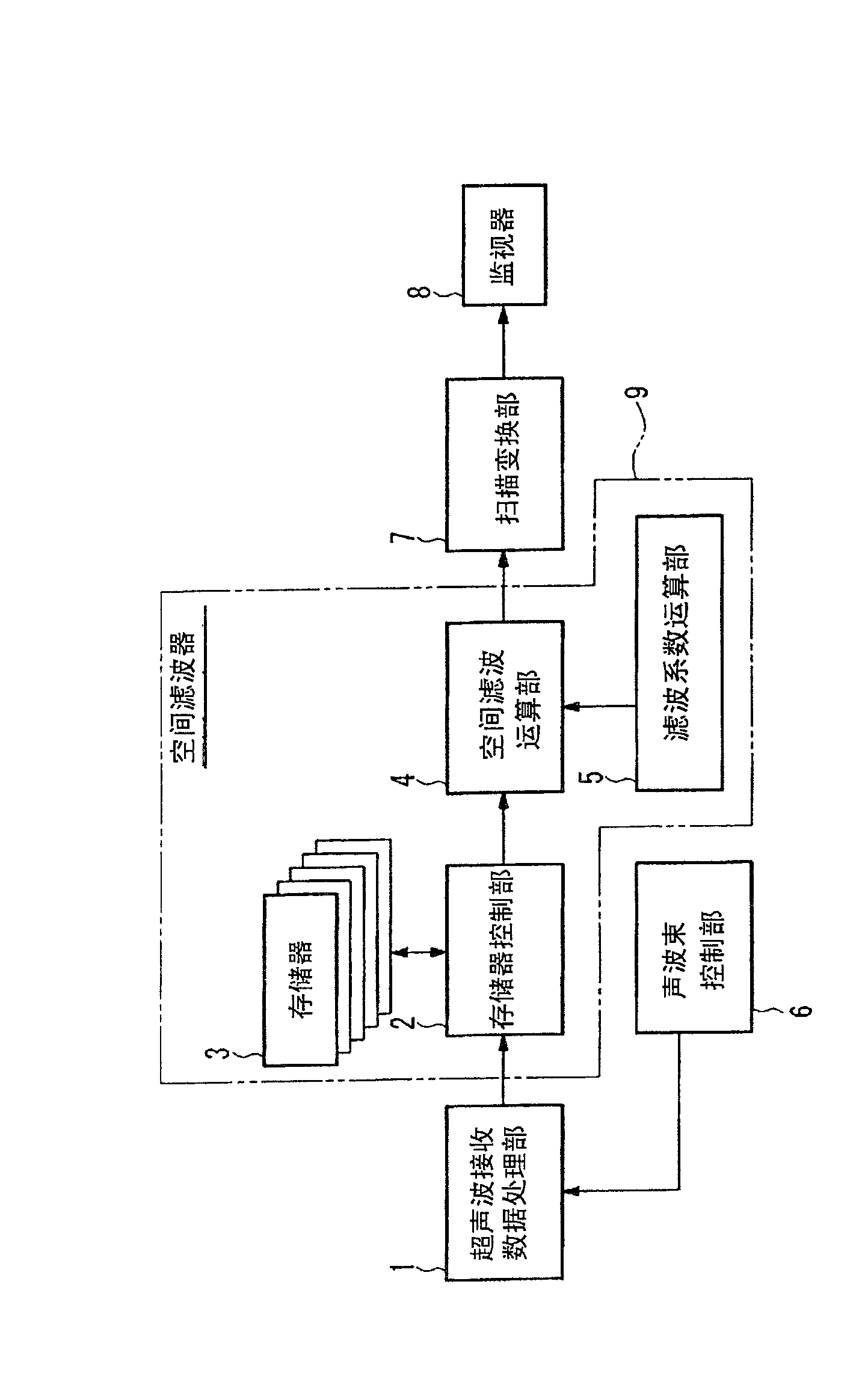
[0060] figure 1 It is a functional block diagram showing a configuration example of the ultrasonic diagnostic apparatus according to the first embodiment of the present invention.
[0061] This ultrasonic diagnostic apparatus is made up of the following parts: Ultrasound reception data processing part 1, forms the reception beam of ultrasonic reception signal, converts the reception beam number into reception beam data; Spatial filter 9; The information of the ultrasonic wave reception data processing unit 1 is provided; the scan conversion unit 7 converts the output data from the spatial filter 9 into image data; and the monitor 8 (display mechanism) displays the image data.
[0062] The spatial filter 9 is composed of a memory 3 (first storage means) for storing received beam data provided from the ultrasonic reception data processing part 1, and a memory control part 2 (first control means) for controlling reading and writing of data in the memory 3. ), a spatial filter c...
no. 2 Embodiment approach
[0120] Figure 6 It is a functional block diagram showing a configuration example of the ultrasonic diagnostic apparatus according to the second embodiment of the present invention. This embodiment relates to an ultrasonic diagnostic apparatus having a two-dimensional Doppler (color Doppler) function. In this ultrasonic diagnostic apparatus, elements for realizing the two-dimensional Doppler function are added to the configuration of the first embodiment. Also, in the following description, the figure 1 The memory control unit 2 is called the first memory control unit 2, and the figure 1 The spatial filter calculation unit 4 is referred to as the first spatial filter calculation unit 4 .
[0121] Elements added by this embodiment will be described below. First, a luminance signal processing unit 10 and a two-dimensional Doppler signal processing unit 11 are provided as elements interposed between the ultrasonic reception data processing unit 1 and the spatial filter 15 ....
no. 3 Embodiment approach
[0126] Figure 7 It is a functional block diagram showing a configuration example of the ultrasonic diagnostic apparatus according to the third embodiment of the present invention. The present embodiment relates to an ultrasonic diagnostic apparatus having a filter coefficient control function corresponding to the depth of reception. In addition to the configuration of the first embodiment, this ultrasonic diagnostic apparatus is provided with a depth information generation unit 17 that supplies received depth information to a filter coefficient calculation unit 16 .
[0127] According to this configuration, it is possible to set different filter coefficients according to the depth of image data. For example, if Figure 8 As shown, when the interval of the acoustic transmission lines 18 differs depending on the depth and thus the interval of the image data D on adjacent acoustic transmission lines 18 differs depending on the depth, the degree of correlation that differs depe...
PUM
 Abstract
Description
Claims
Application Information
 - Generate Ideas
- Intellectual Property
- Life Sciences
- Materials
- Tech Scout
- Unparalleled Data Quality
- Higher Quality Content
- 60% Fewer Hallucinations
Browse by: Latest US Patents, China's latest patents, Technical Efficacy Thesaurus, Application Domain, Technology Topic, Popular Technical Reports.
© 2025 PatSnap. All rights reserved.Legal|Privacy policy|Modern Slavery Act Transparency Statement|Sitemap|About US| Contact US: help@patsnap.com


