Glass plate manufacturing method and glass plate manufacturing apparatus
A manufacturing method and glass plate technology, applied in glass manufacturing equipment, glass forming, glass forming, etc., can solve the problems of streaks in the direction of glass plate conveyance, control the temperature of the atmosphere in the slow cooling space to the desired temperature distribution, etc., and achieve The effect of suppressing streaks
- Summary
- Abstract
- Description
- Claims
- Application Information
AI Technical Summary
Problems solved by technology
Method used
Image

Examples
Embodiment approach 1
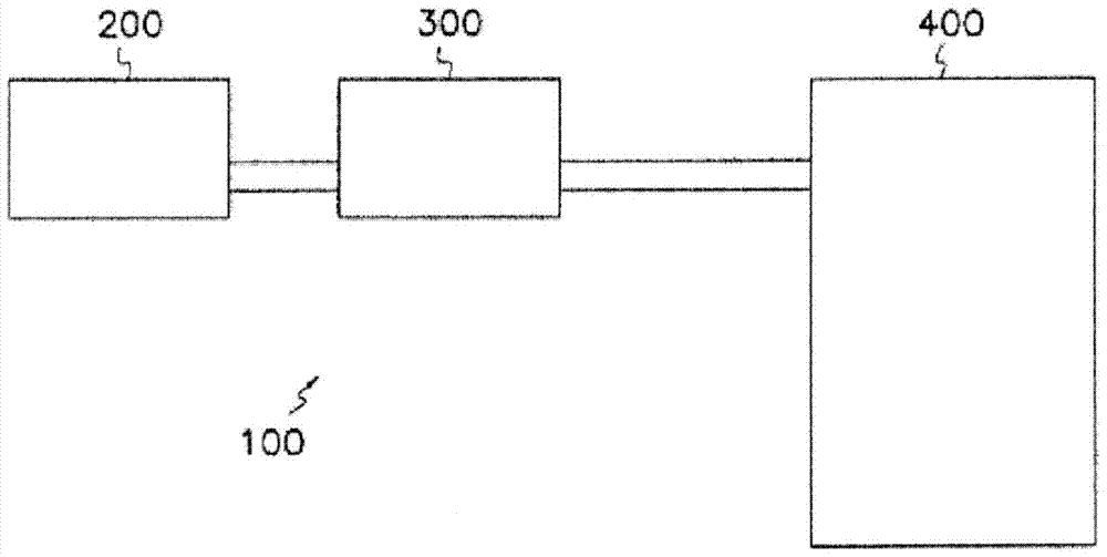
[0091] Hereinafter, the manufacturing method of the glass plate which concerns on this embodiment, and the manufacturing apparatus of a glass plate are demonstrated. figure 1 It is a schematic structural diagram of the glass plate manufacturing apparatus of this embodiment.
[0092] Such as figure 1 As shown, the glass plate manufacturing apparatus 100 includes a melting tank 200 , a clarification tank 300 , and a forming device 400 . The raw material of glass is melt|dissolved in the melting tank 200, and molten glass is produced. The molten glass produced in the melting tank 200 is sent to the clarification tank 300 . Bubbles contained in the molten glass are removed in the clarification tank 300 . The molten glass from which air bubbles have been removed in the clarification tank 300 is sent to the forming apparatus 400 . The forming apparatus 400 continuously forms a glass sheet G from molten glass by, for example, an overflow downdraw method. Thereafter, the shaped g...
Embodiment approach 2
[0119] Next, when the heat insulating member 40 is formed integrally, the method of suppressing the streak GS of the glass plate G by providing the heat insulating board 41 along the heat insulating member 40 is demonstrated. In addition, the description of the configuration common to the above-mentioned embodiment is omitted.
[0120] Figure 9 It is a schematic diagram at the time of planarly seeing the heat insulating member which sandwiched the glass plate of this embodiment. As shown in the figure, the heat insulating board 41 is provided along the heat insulating member 40 . The heat insulation board 41 can be installed so that it may insert into the inside of the slow cooling zone 420 from the slit which carries out the glass plate G formed in the lower end of the slow cooling space 42h, for example. In addition, the method of installing the heat insulation board 41 can be changed arbitrarily according to the structure of the forming zone 42a and the annealing zone 42...
Embodiment approach 3
[0124] Next, a method for suppressing streaks generated between the edge G1 and the center region G2 of the glass sheet G will be described. In addition, the description of the configuration common to the above-mentioned embodiment is omitted.
[0125] Such as Figure 4 As shown, the glass plate G includes a central region G2 having a substantially uniform thickness, and an end portion G1 having a thickness greater than the central region G2. Both ends G1 have a thickness greater than that of the central region G2, which is substantially uniform in thickness, so the retained heat is greater than that of the central region G2, and there is a difference in the retained heat between the both ends G1 and the central region G2. Stress is generated between them, and warpage and strain are generated in the glass plate G. Therefore, the streak GS (strain) is reduced by making the retained heat amount of both end portions G1 and the central region G2 equal. Such as Figure 8 As sho...
PUM
| Property | Measurement | Unit |
|---|---|---|
| thickness | aaaaa | aaaaa |
| strain point | aaaaa | aaaaa |
Abstract
Description
Claims
Application Information
 - Generate Ideas
- Intellectual Property
- Life Sciences
- Materials
- Tech Scout
- Unparalleled Data Quality
- Higher Quality Content
- 60% Fewer Hallucinations
Browse by: Latest US Patents, China's latest patents, Technical Efficacy Thesaurus, Application Domain, Technology Topic, Popular Technical Reports.
© 2025 PatSnap. All rights reserved.Legal|Privacy policy|Modern Slavery Act Transparency Statement|Sitemap|About US| Contact US: help@patsnap.com