Rod lens array and image sensor head using rod lens array
一种图像传感器、棒状透镜的技术,应用在透镜、图像通信、仪器等方向,能够解决难以谋求光学系统小型化等问题,达到抑制电力消耗、图像均匀、抑制条斑的效果
- Summary
- Abstract
- Description
- Claims
- Application Information
AI Technical Summary
Problems solved by technology
Method used
Image

Examples
Embodiment 1
[0212] 43.5 parts by mass of polymethyl methacrylate (PMMA), 15.5 parts by mass of methyl methacrylate (MMA), 7.5 parts by mass of phenyl methacrylate (PhMA), 3.5 parts by mass of tert-butyl methacrylate (TBMA) , tricyclic methacrylate [5.2.1.0 2,6 ] 30 parts by mass of decyl ester (TCDMA), 0.25 parts by mass of 1-hydroxycyclohexyl phenyl ketone (HCPK), and 0.1 part by mass of hydroquinone (HQ) were heated to 70° C. and kneaded to obtain the first layer. Stock solution (uncured substance).
[0213] 44 parts by mass of PMMA, 17 parts by mass of MMA, 8 parts by mass of PhMA, 5.5 parts by mass of TBMA, 25.5 parts by mass of TCDMA, 0.25 parts by mass of HCPK, and 0.1 parts by mass of HQ are heated to 70°C and kneaded to form the second layer Use stock solution (uncured substance).
[0214]46 parts by mass of PMMA, 16.5 parts by mass of MMA, 11 parts by mass of PhMA, 8.5 parts by mass of TBMA, 12.5 parts by mass of TCDMA, 5.5 parts by mass of 2,2,3,3-tetrafluoropropyl methacrylat...
Embodiment 2
[0239] The cured filament was stretched to 2.34 times at a temperature of 145° C., and then relaxed at a temperature of 127° C. so that the relaxation rate became 0.71. Other conditions were the same as in Example 1. rod lens.
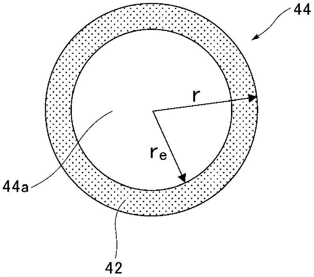
[0240] The radius r of the rod lens obtained in this way is 0.232mm, and the central refractive index n 0 When the wavelength is 525nm, it is 1.503, and the refractive index distribution in the range of 0.2r ~ 0.9r from the center to the outer periphery is similar to the above formula related to the refractive index distribution. When the wavelength is 525nm, the refractive index distribution constant g is 0.43mm -1 . Also, a dye-infused layer is formed from the outer periphery toward the center, and the effective radius r e is 0.220mm, and the numerical aperture NA of the lens is 0.142.
[0241] Using 684 obtained rod lenses, a one-row rod lens array having a lens length of 8.8 mm and an array pitch P of 0.468 mm (the gap between adjacent lenses b...
Embodiment 3
[0246] The cured filament was stretched to 4.11 times at a temperature of 145°C, and then relaxed at a temperature of 127°C so that the relaxation rate became 0.71. Other conditions were the same as in Example 1. rod lens.
[0247] The radius r of the rod lens obtained in this way is 0.175mm, and the central refractive index n 0 When the wavelength is 525nm, it is 1.503, and the refractive index distribution in the range of 0.2r ~ 0.9r from the center to the outer periphery is similar to the above formula related to the refractive index distribution. When the wavelength is 525nm, the refractive index distribution constant g is 0.57 mm -1 . Also, a dye-infused layer is formed from the outer periphery toward the center, and the effective radius r e It is 0.166mm, and the numerical aperture NA of the lens is 0.142.
[0248] Using 914 obtained rod lenses, a one-row rod lens array having a lens length of 6.7 mm and an array pitch P of 0.350 mm (a gap between adjacent lenses: 0 ...
PUM
 Abstract
Description
Claims
Application Information
 - Generate Ideas
- Intellectual Property
- Life Sciences
- Materials
- Tech Scout
- Unparalleled Data Quality
- Higher Quality Content
- 60% Fewer Hallucinations
Browse by: Latest US Patents, China's latest patents, Technical Efficacy Thesaurus, Application Domain, Technology Topic, Popular Technical Reports.
© 2025 PatSnap. All rights reserved.Legal|Privacy policy|Modern Slavery Act Transparency Statement|Sitemap|About US| Contact US: help@patsnap.com