
Automatic DNA reaction solution draining device

A reaction solution and automatic discharge technology, applied in the field of bioengineering, can solve problems affecting the accuracy of calculation results, insufficient solution volume, biological pollution, etc., to overcome solution leakage and residual problems, avoid pipeline pollution, and ensure correctness Effect

Inactive Publication Date: 2009-08-19
SHANGHAI JIAOTONG UNIV
View PDF5 Cites 0 Cited by
  • Summary
  • Abstract
  • Description
  • Claims
  • Application Information

AI Technical Summary

Problems solved by technology

Large leakage, when the result solution is extracted, the amount of solution obtained is less than expected, or even not obtained at all, resulting in insufficient solution amount during bioelectrochemical chip detection; large residues will cause biological contamination and seriously affect the calculation results correctness

Method used


Image

  • Automatic DNA reaction solution draining device

Examples


Embodiment Construction

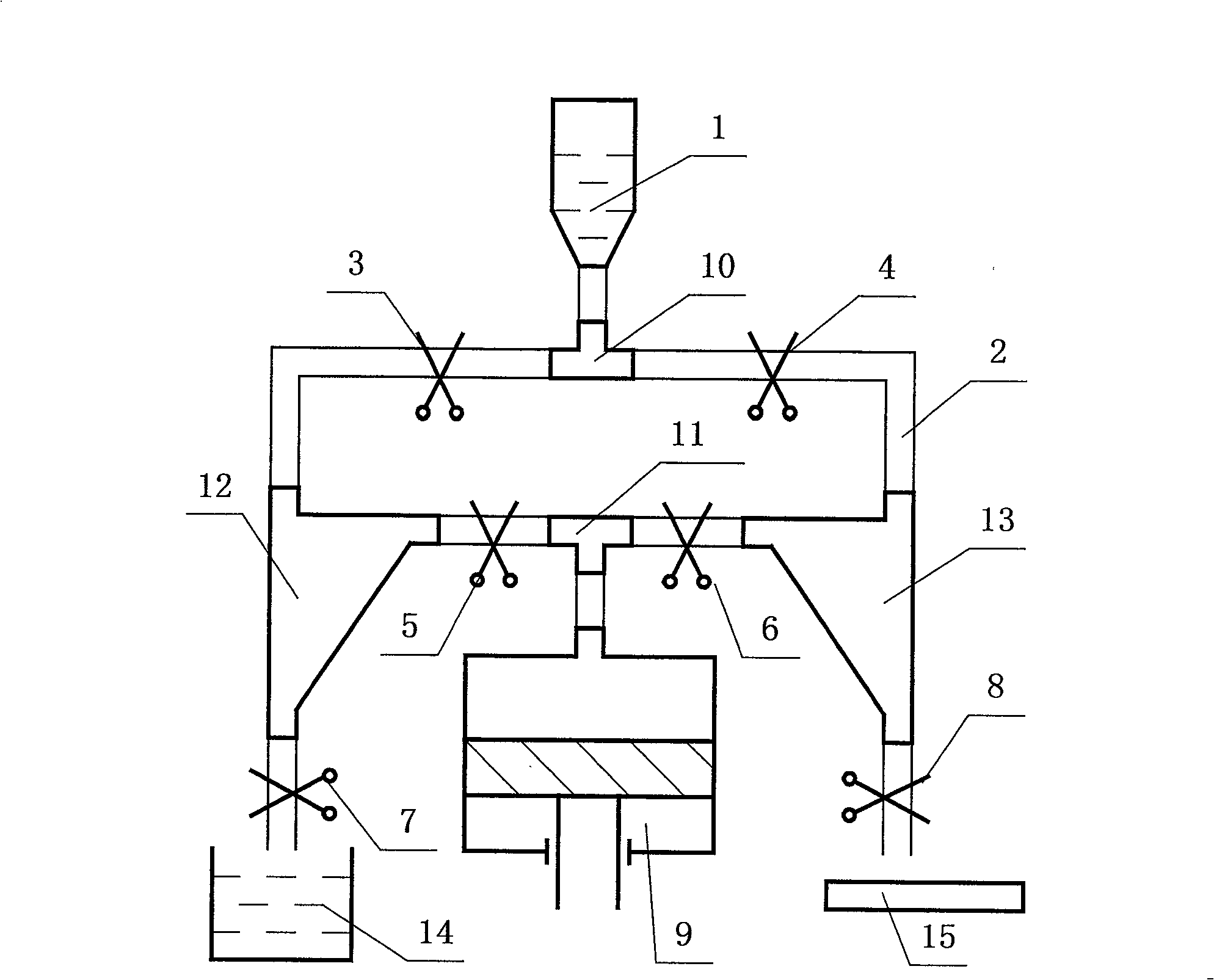
[0015] Such as figure 1 As shown, the present invention includes: reaction tank 1, plastic hose 2, first tee 10, second tee 11, waste liquid pool 14, is characterized in that, also includes: piston pump 9, first electromagnetic clip 3, The second electromagnetic clamp 4 , the third electromagnetic clamp 5 , the fourth electromagnetic clamp 6 , the fifth electromagnetic clamp 7 , the sixth electromagnetic clamp 8 , the first solution chamber 12 , the second solution chamber 13 , and the bioelectrochemical chip 15 .

[0016] The reaction pool 1 is connected to the first solution chamber 12 and the second solution chamber 13 through the first three-way 10 and two plastic hoses 2, and the piston pump 9 is connected to the first solution chamber 13 through the second three-way 11 and two plastic hoses 2. The solution chamber 12 is connected to the second solution chamber 13, the first solution chamber 12 is also connected to the waste liquid pool 14 through a plastic hose 2, and th...


PUM


Abstract

The automatic solution draining device for automatic DNA calculating machine includes one reaction tank, plastic hoses, six electromagnetic clamps, one piston pump, two T-pipes, two solution cavities, one waste liquid tank, and electrochemical biochips connected together. The present invention has simple structure and reliable operation, and can meet the requirement of no residue and no leakage of solution draining treatment during DNA calculating reaction.

Description

technical field [0001] The invention relates to a device in the technical field of bioengineering, in particular to a DNA reaction solution automatic discharge device. Background technique [0002] DNA (deoxyribonucleic acid) computing technology, simply put, is based on the unique combination of DNA double helix structure, artificially recombines and arranges the four base pairs of DNA molecules, so as to realize the function of numerical and logical operations. The medium to complete this operation is a DNA chain, so it is called DNA computing. The process of DNA computing is the process of placing DNA molecules in the reaction pool to make them react and process in a specific solution. During DNA calculation, solutions such as sample solution, buffer, ligase and sodium hydroxide need to be added to the reaction cell. In the reaction pool, the intermediate process waste liquid is generated first, and then the final result solution to be tested; after a calculation is com...

Claims


Application Information

Patent Timeline
Patent Type & Authority Patents(China)
IPC IPC(8): C12M1/00C12Q1/68
Inventor 徐威王新洪王石刚
Owner SHANGHAI JIAOTONG UNIV
Learn More