Linear type heat treatment furnace

A heat treatment furnace, linear technology, applied in heat treatment furnaces, heat treatment equipment, furnaces, etc., can solve the problems of increasing cleaning processes and cleaning equipment, longer loss time, and high cost, shortening waiting time, preventing atmosphere fluctuations, extending The effect of service life

Active Publication Date: 2009-07-15
东宇东庵(无锡)科技有限公司
View PDF5 Cites 0 Cited by
  • Summary
  • Abstract
  • Description
  • Claims
  • Application Information

AI Technical Summary

Problems solved by technology

However, in order to meet the individual conditions of each room, the standby time and the time of forward movement are unstable, and deformation such as roller sinking occurs due to high temperature, regardless of the size of the bracket with the workpiece, and all of them are often started at the same time at a certain time. The rollers are in a forward state, so there are many problems. Only the heat-treated workpiece is controlled to stay inside the heat treatment furnace, but the transfer speed of the workpiece in the furnace cannot be controlled, and the loss time when changing the cycle becomes longer, and the expected quality cannot be obtained. Therefore, Poor quality products are produced in the workpiece
[0012] In the linear heat treatment furnace of the prior art, the workpiece needs to be cleaned first to remove oil stains and then enter the preheating chamber, which increases the cleaning process and cleaning equipment, and the cost is high

Method used


Image

  • Linear type heat treatment furnace
  • Linear type heat treatment furnace
  • Linear type heat treatment furnace

Examples


Embodiment Construction

[0045] The present invention will be described in detail below with reference to the drawings and examples.

[0046] In the drawings, the same symbols are used for the same components as those of the prior art.

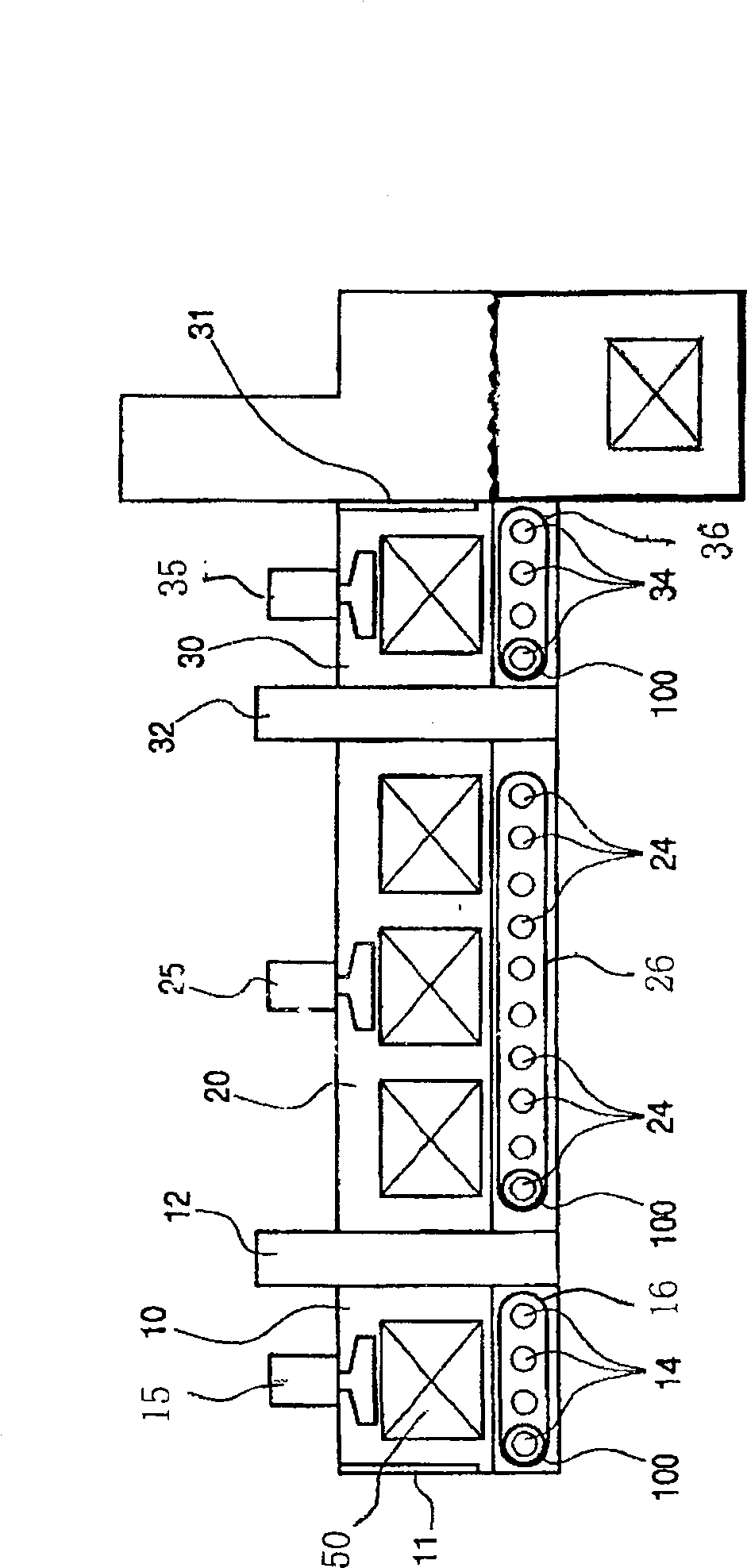
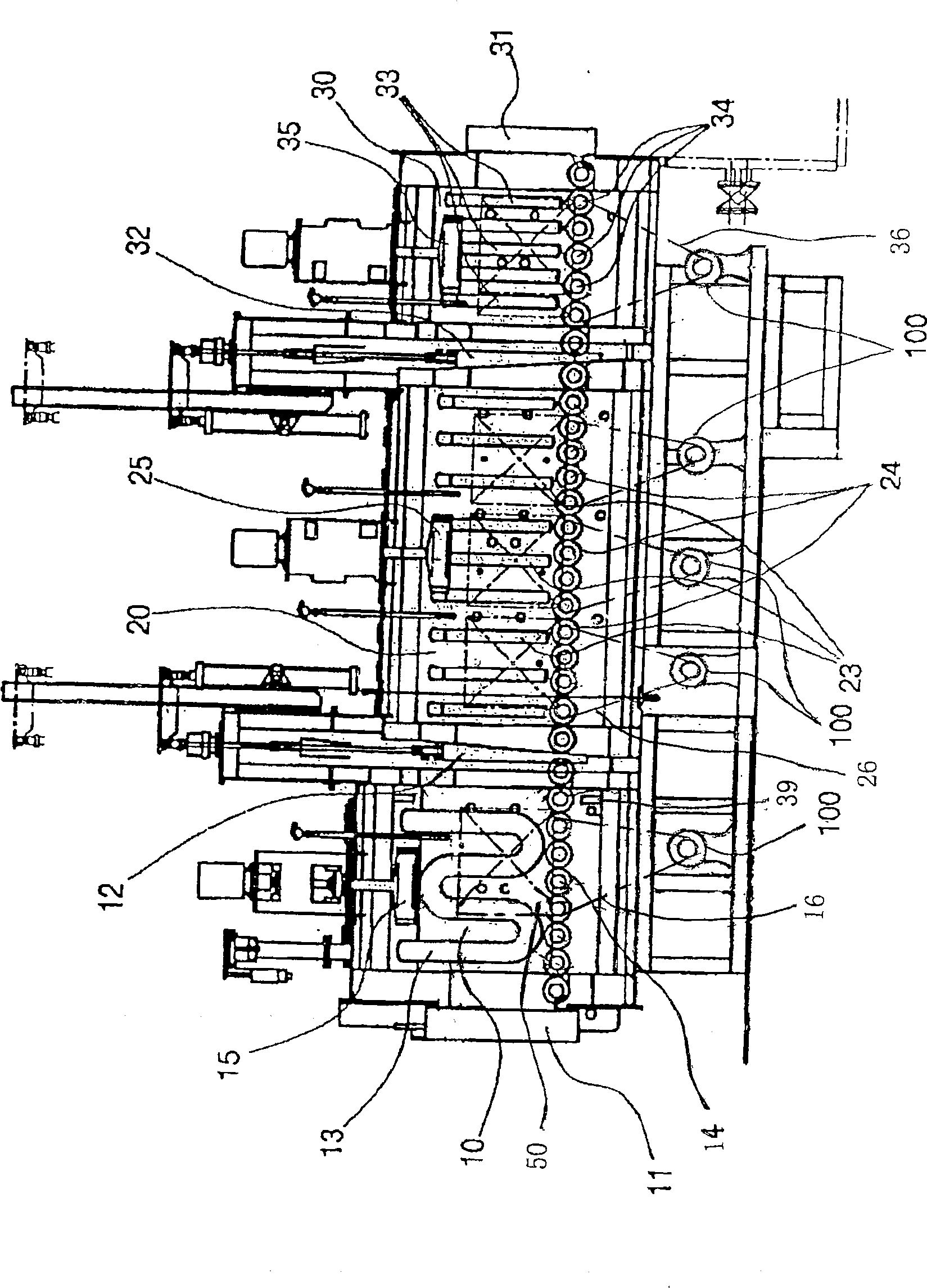
[0047] The linear heat treatment furnace of the present invention is as Figure 2 to Figure 5 as shown, figure 2 It is a structural schematic diagram of the linear heat treatment furnace of the present invention. Such as figure 2 As shown, the present invention is a linear heat treatment furnace composed of a preheating chamber 10, a heat treatment chamber 20 and a quenching chamber 30. First of all, let me explain one thing: each room and each station are in the figure 2 , Figure 5 is represented by a square frame surrounded by dotted lines.

[0048] The preheating chamber 10 forms a sealed space by the entrance door 11 that cuts off the loading port for loading the workpiece 50 from the outside, and the first partition door 12 that separates the heat treat...


PUM


Abstract

A linear heat treatment furnace, including a preheating chamber for workpiece preheating, a heat treatment chamber for carburizing the workpiece, and a quenching chamber for quenching and hardening of the workpiece; each chamber is sealed and rollers and circulation fans are installed in the chamber; heat treatment The electric heater is installed in the quenching chamber and the quenching chamber; the preheating chamber is equipped with a gas burner; in addition, each chamber of the preheating chamber, heat treatment chamber and quenching chamber is equipped with an independent motor at each station and rotates forward under the drive of the motor and chain. Or when the workpiece arrives at the designated station, a set of rollers and two intersecting photoelectric sensors that rotate forward or backward by 180° at regular intervals. Therefore, the traveling speed of workpieces in each chamber can be adjusted according to the heat treatment process; the waiting time can be shortened and empty brackets can be avoided. And the atmosphere gas and cycle time of each chamber can be controlled separately. Prevent the atmosphere from fluctuating, so that the workpiece can be carburized uniformly, and the metallographic phase is uniform, making it a high-quality product. At the same time, the service life of the roller is extended.

Description

technical field [0001] The invention belongs to a furnace for metal heat treatment, in particular to a furnace consisting of a preheating chamber, a heat treatment chamber and a quenching chamber. Each chamber is equipped with an independent motor at each station, and is driven by the motor and a chain to rotate forward or the workpiece to reach a specified position. When working at the station, turn forward or backward 180 degrees at regular intervals 0 A set of rollers and two cross photoelectric sensors. The speed of the workpiece is controlled according to the heat treatment process, and the atmosphere gas, cycle time, temperature, etc. of each chamber can be controlled separately to prevent atmosphere fluctuations, make the metal structure of the workpiece uniform, and obtain better products. Linear heat treatment furnace. Background technique [0002] The discovery of metals had a considerable influence on the development of human civilization, and humans used metals ...

Claims


Application Information

Patent Timeline
Patent Type & Authority Patents(China)
IPC IPC(8): C21D9/00C21D1/78C23F17/00C21D1/62
Inventor 崔中赫
Owner 东宇东庵(无锡)科技有限公司
Why Eureka
Try Eureka