Lathe dedicated for boring on pipe fittings flange

A special machine tool and flange technology, applied in the field of special machine tool equipment for pipe flange drilling, can solve the problems of reduced life, easy wear of drill bits and drill sleeves, increased labor intensity of operators, etc., and achieves simple processing technology and assembly technology. , to solve the effect of low work efficiency

Inactive Publication Date: 2009-07-01
北京通州宋庄铸造厂
View PDF6 Cites 1 Cited by
  • Summary
  • Abstract
  • Description
  • Claims
  • Application Information

AI Technical Summary

Problems solved by technology

[0003] The clamping parts are clamped and loosened by manual operation, and the position must be corrected manually, which increases the labor intensity of the operator, and because this kind of processing, the combination of the drilling template and the workpiece is guaranteed by the operator's work experience and technology , so the position error of drilling is relatively difficult to guarantee, resulting in larger correction errors and increased auxiliary time
[0004] Since the existing technology is to process single holes sequentially, the rocker arm is moved to the position of another hole after one hole is completed. In this way, when the position is found, the drill bit collides with the drill sleeve, and the friction is serious, which is easy to wear the drill bit and the drill sleeve. Sets will reduce the lifespan and increase the auxiliary time when moving to find the correct position

Method used


Image

  • Lathe dedicated for boring on pipe fittings flange
  • Lathe dedicated for boring on pipe fittings flange
  • Lathe dedicated for boring on pipe fittings flange

Examples


Embodiment Construction

[0034] The technical scheme of the present invention will be described in detail below in conjunction with the accompanying drawings.

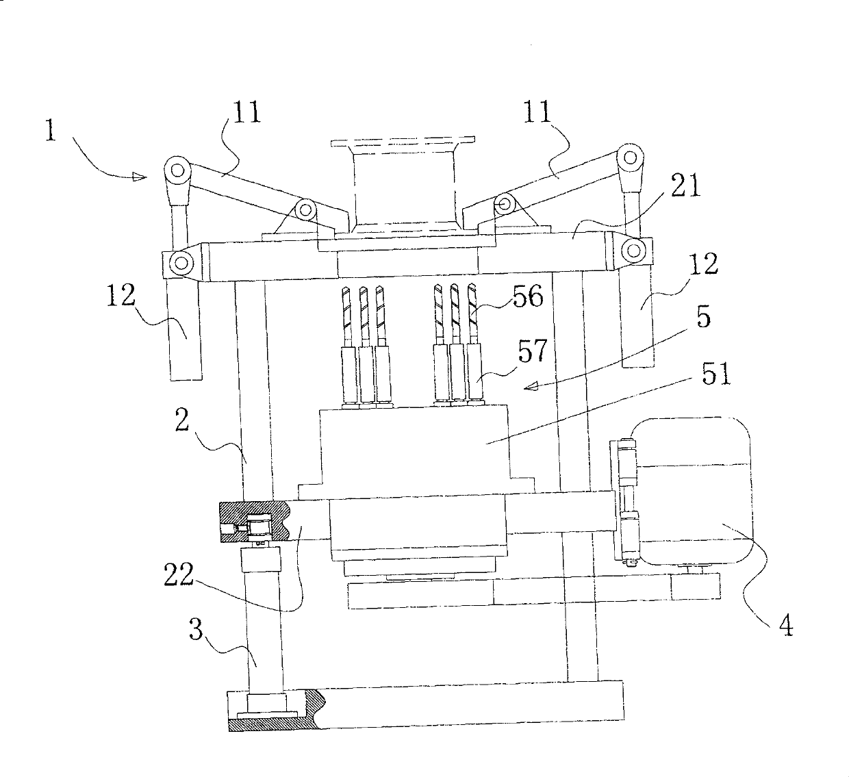
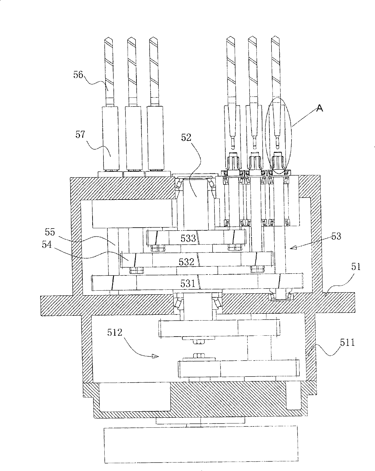
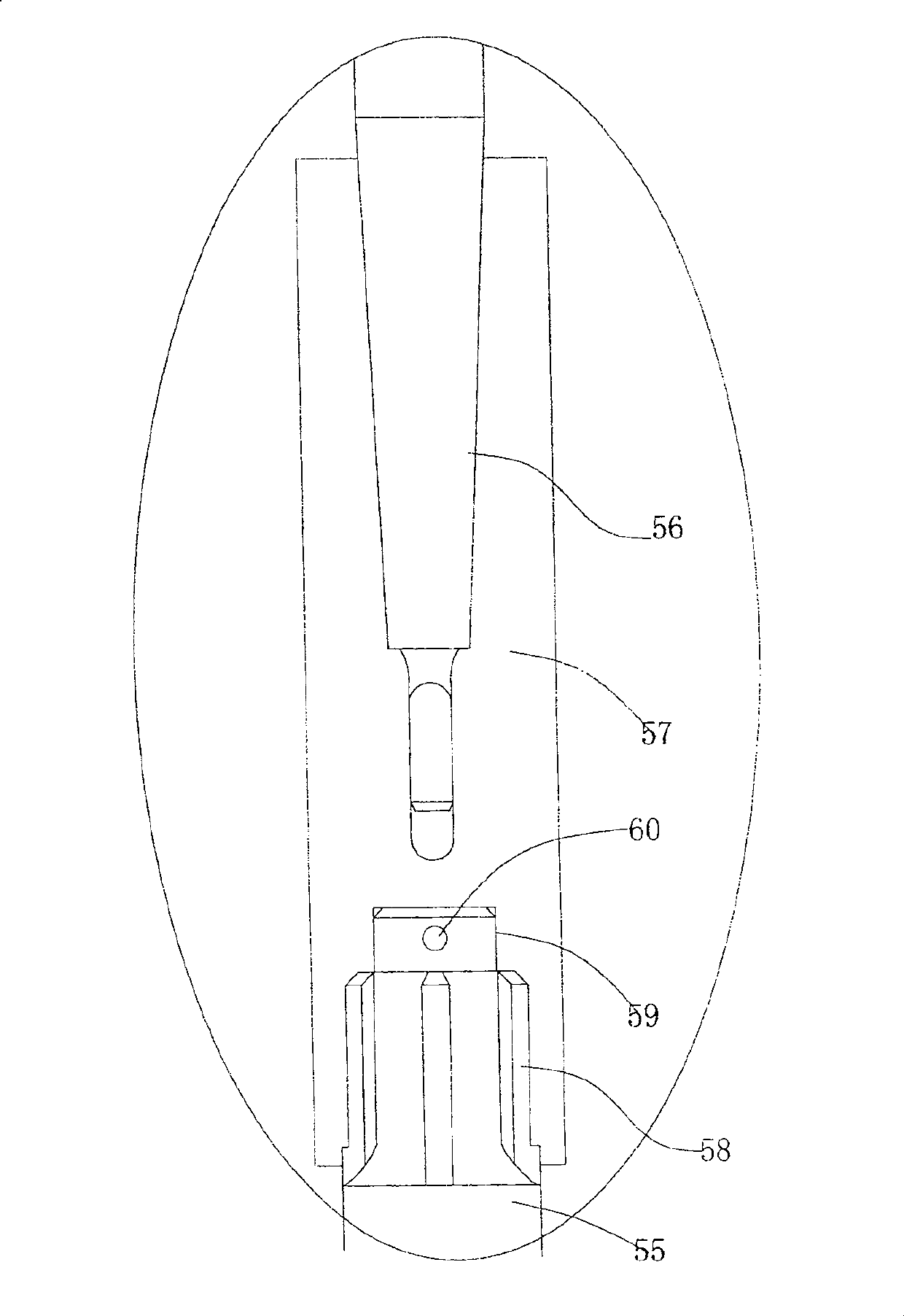
[0035] The invention provides a special machine tool for drilling holes in pipe fitting flanges, referring to figure 1 and figure 2 , the special machine tool mainly includes: fixture part 1, frame part 2, hydraulic system 3, electromechanical transmission system 4, multi-axis power head part 5, and the multi-axis power head 5 further includes: spindle box 51, main drive shaft 52 , Tower-shaped gear set 53, this tower-shaped gear set further includes three driving wheels 531 (large), 532 (middle), 533 (small), and the planetary gears that are symmetrically distributed on the outer circumference of the three driving wheels and meshed with it 54 and the drilling main shaft 55 installed on the planetary wheel, the rotation of the drilling main shaft 55 (main movement) is transmitted to the reduction gear set 512 of the lower transmission case 5...


PUM


Abstract

The invention discloses a special machine tool for drilling flanges of pipe fittings, which includes frame parts, electromechanical transmission systems, fixture parts, hydraulic systems, and electrical systems. The components include: a headstock, installed on the middle plate of the frame part; a tower gear set, installed on the main transmission shaft in the headstock; the tower gear set further includes: a plurality of driving wheels , installed on the main transmission shaft in the headstock; a plurality of planetary wheels, symmetrically distributed on the outer circumference of the plurality of driving wheels and meshed with the plurality of driving wheels; and a plurality of main shafts, respectively installed on the planetary wheels Above; the electromechanical transmission system drives the main transmission shaft of the headstock, and the main transmission shaft sequentially drives the main shaft on the plurality of planetary gears to rotate through the tower gear set. The invention realizes one-time multi-hole processing of the flange of the pipe fitting, and both the work efficiency and the drilling quality are effectively improved.

Description

technical field [0001] The invention relates to machine tool technology, in particular to a special machine tool equipment for drilling flanges of pipe fittings. Background technique [0002] Drilling machines commonly used in the pipe fitting flange drilling method of the prior art are such as: Z32K, Z3050, Z3080 radial drilling machines, and the flange holes are processed with a single hole of the drilling die. The processing method of the prior art has the following disadvantages: [0003] The clamping parts are clamped and loosened by manual operation, and the position must be corrected manually, which increases the labor intensity of the operator, and because this kind of processing, the combination of the drilling template and the workpiece is guaranteed by the operator's work experience and technology , so the position error of drilling is relatively difficult to guarantee, resulting in larger correction errors and increased auxiliary time. [0004] Since the existin...

Claims


Application Information

Patent Timeline
Patent Type & Authority Patents(China)
IPC IPC(8): B23B41/00B23B39/16B23B47/30B23B47/04B23Q3/06B23Q3/12B23B47/22
Inventor 殷宝海殷震浩张连弟牛炳辉
Owner 北京通州宋庄铸造厂
Why Eureka
Try Eureka