Microstructure bidirection bending pulling fatigue experimental device

A fatigue test and microstructure technology, applied in the field of basic research of micro-nano technology, can solve the problems of difficult and impossible clamping and centering of micron-sized samples

Inactive Publication Date: 2009-05-06
BEIJING UNIV OF TECH
View PDF4 Cites 0 Cited by
  • Summary
  • Abstract
  • Description
  • Claims
  • Application Information

AI Technical Summary

Problems solved by technology

However, this method is not suitable for the study of MEMS fatigue characteristics. First, the driving methods of hydraulic pressure and electromagnetic force are not suitable for the state of micron size. impossible to complete

Method used


Image

  • Microstructure bidirection bending pulling fatigue experimental device
  • Microstructure bidirection bending pulling fatigue experimental device
  • Microstructure bidirection bending pulling fatigue experimental device

Examples


Embodiment Construction

[0031] Specific embodiments of the present invention are described below in conjunction with accompanying drawing:

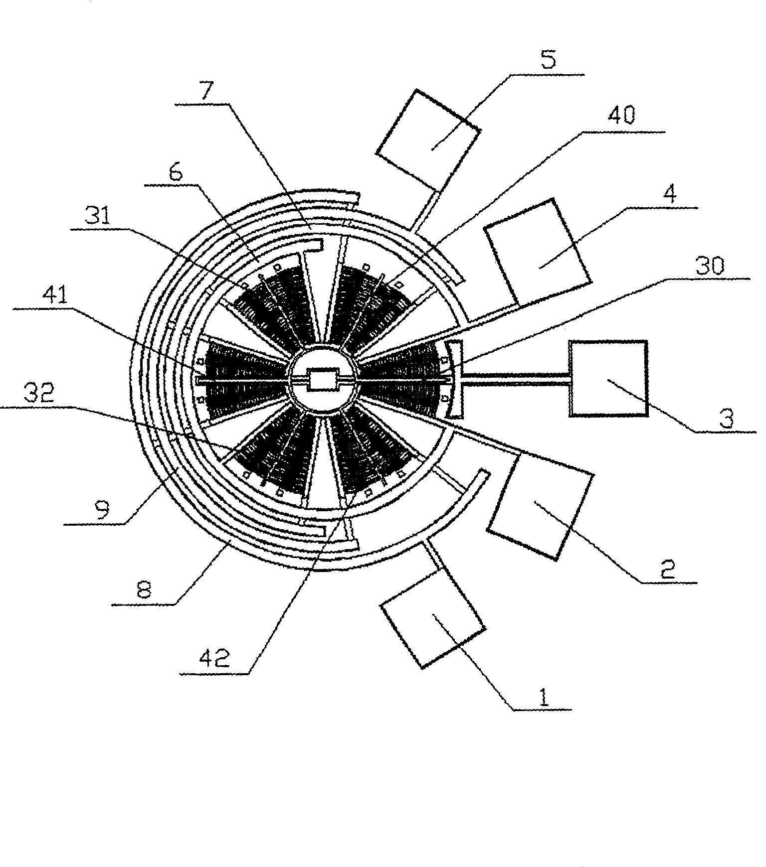
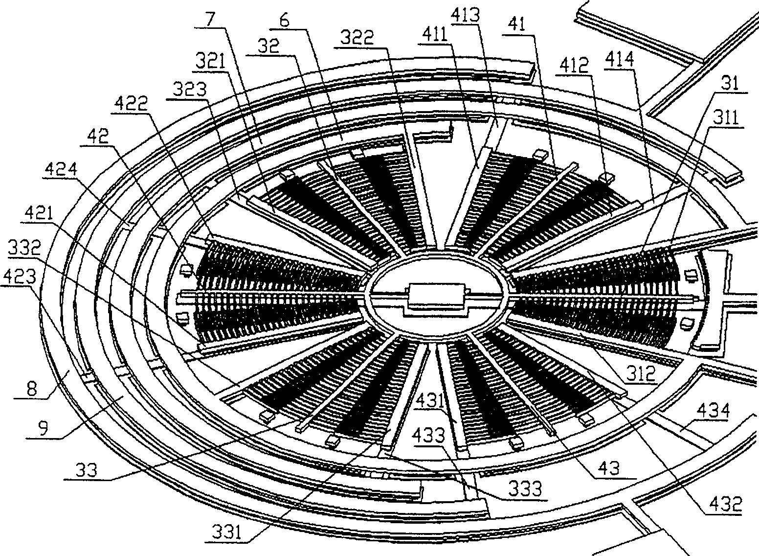
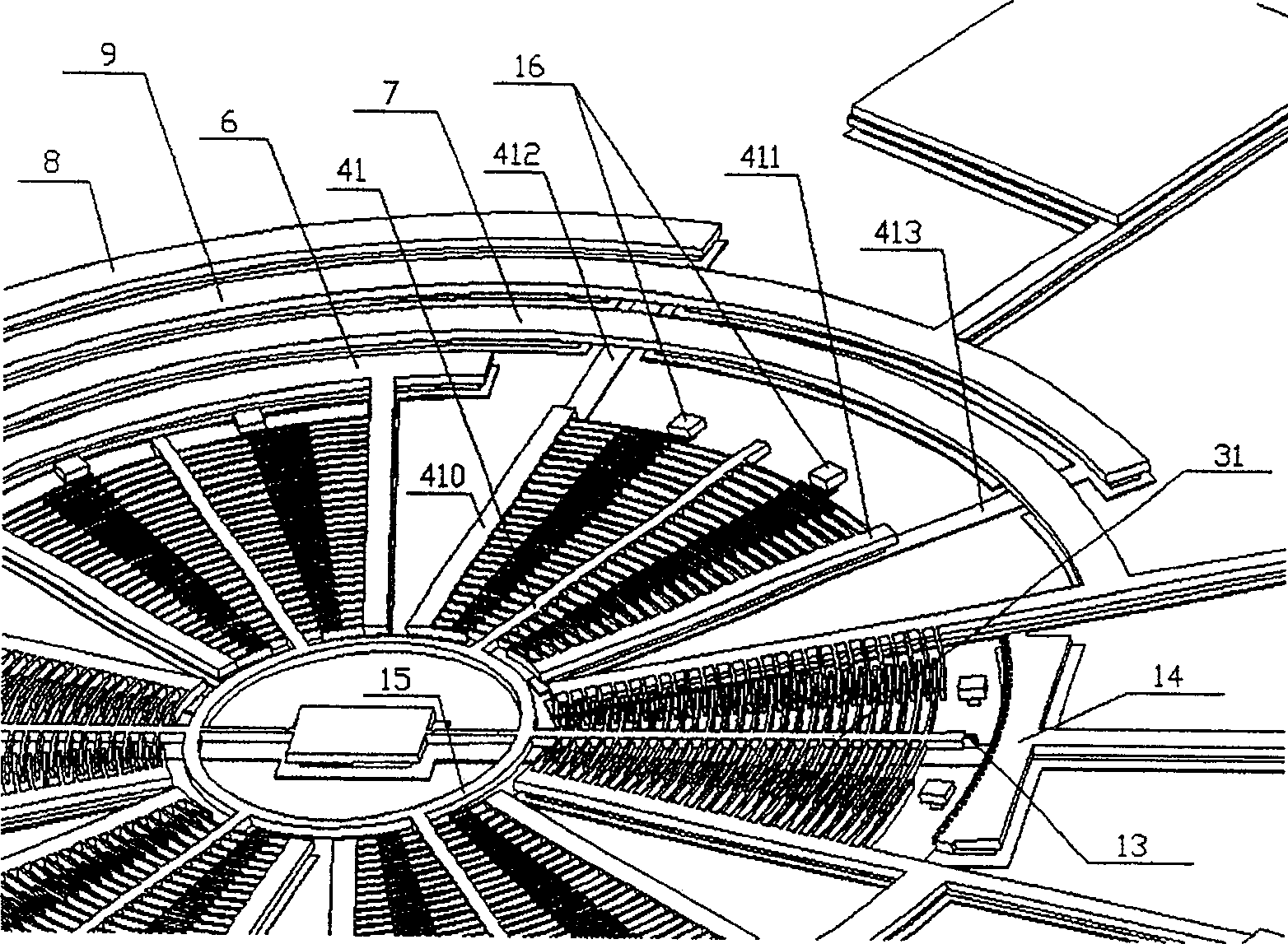
[0032] The structural diagram of the microstructure bi-directional bending-tensile fatigue test device designed according to the idea of ​​this technical scheme can be found in figure 1 , figure 2 , image 3 , Figure 4 , Figure 5 , Figure 6 shown. figure 1 is the frontal global map, figure 2 , image 3 It is a partial enlarged view of the main structural part, and its maximum characteristic size is about 1000 μm. Figure 4 is the structural diagram of all suspended vibrating parts, Figure 5 is the enlarged morphology of the sample, Figure 6 It is a cross-sectional view of each layer structure of the electrode. The whole device is distributed in a disk shape, 1, 2, 3, 4, 5 are five electrodes, of which 2, 4 are driving electrodes, connected to the ring arms 6, 7 respectively, 1, 5 are detection electrodes, respectively connected to the ring arms ...


PUM


Abstract

A two - way bending fatigue test device of microstructure is prepared as distributing six broach units at multiple nonclosed disc ring arms with the same circular center and different diameter, using said units as driving set to drive suspension structure and as detecting set to measure swing amplitude of suspension structure separately, forming each board unit by a suspension board and two fixed broaches at two sides of suspension broach, connecting suspension broach to DC electrode and fixed broach to driving electrode, connecting two AC with the same frequency and opposite phase separately to driving electrode.

Description

technical field [0001] The invention is used for the research on the fatigue characteristics of polysilicon, a structural material of MEMS (Micro-Electro-Mechanical System, micro-electro-mechanical system), and belongs to the field of basic research of micro-nano technology. Background technique [0002] Studies have found that silicon, which is a brittle material in the macroscopic state, will produce fatigue characteristics at the micro-nano scale, and the mechanism of this change is not yet clear. Understanding this mechanism and measuring the fatigue characteristic parameters of silicon at the micron scale are of great significance for the reliability design and life prediction of MEMS. [0003] At the current scale that MEMS can reach, many physical phenomena are very different from the macroscopic world due to the impact of size reduction (Scaling Effects), so it is necessary to study microdynamics, microfluidics, microthermodynamics, In-depth research in optics, micr...

Claims


Application Information

Patent Timeline
Patent Type & Authority Patents(China)
IPC IPC(8): G01N3/38
Inventor 丁雷尚德广贾冠华孙国芹李浩群
Owner BEIJING UNIV OF TECH
Why Eureka
Try Eureka