Valve device

A valve device and connecting device technology, applied in valve device, valve operation/release device, valve details, etc., can solve problems such as the influence of valve device manipulation and adjustment characteristics, the inability to accurately determine the position of valve components, and high dynamic motion.

Inactive Publication Date: 2009-02-11
ROBERT BOSCH GMBH
View PDF7 Cites 0 Cited by
  • Summary
  • Abstract
  • Description
  • Claims
  • Application Information

AI Technical Summary

Problems solved by technology

[0008] However, there is also the disadvantage here that when the valve device is in operation, there can be axial and radial relative movements between the armature and the valve element, so that the position of the valve element with respect to the position of the armature cannot be precisely determined for the entire operating range of the valve device , and when the valve device is in operation, the valve element generates vibrations and other highly dynamic movements due to its small mass, which negatively affects the operating and adjustment characteristics of the valve device

Method used


Image

  • Valve device

Examples


Embodiment Construction

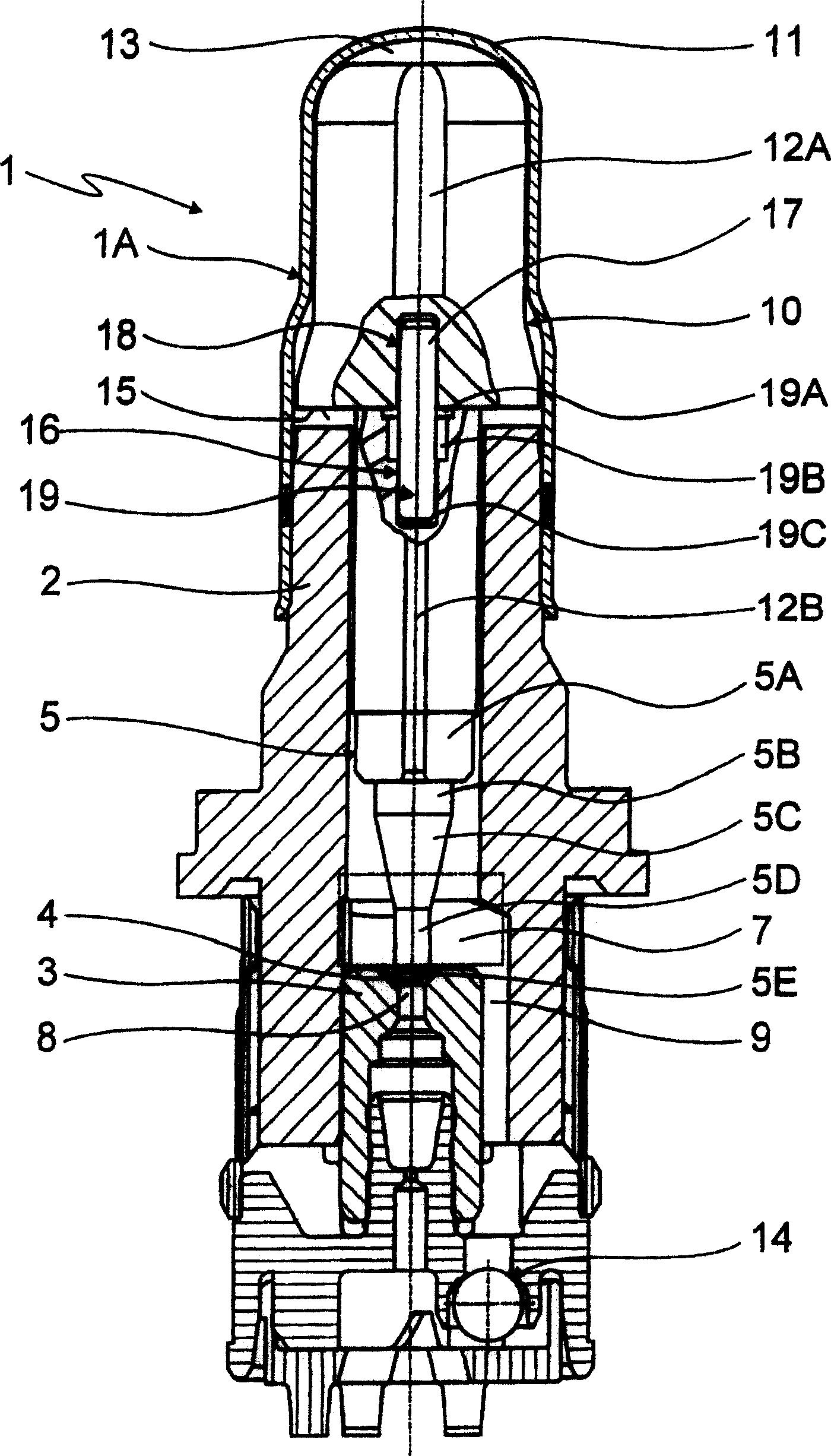
[0016] The figure shows a part of the electromagnetically operable valve device 1 in a simplified longitudinal section. The valve device 1 has a valve element 5 that is longitudinally movable in the valve bush 2 and cooperates with a valve seat 4 formed in the valve body 3.

[0017] The area of ​​the valve element 5 facing the valve seat 4 is located in the valve cavity 7 defined by the valve bushing 2 in the area of ​​the valve seat 4, wherein the outline size of the valve cavity is further shown by the rectangle drawn with a dotted line in Figure 1. The area of ​​the element 5 facing the valve cavity 7 has a first cylindrical area 5A, a second cylindrical area 5B resting on the cylindrical area 5A and having a reduced diameter, and a conical area 5C connected to the second cylindrical area 5B , The third cylindrical area 5C connected to the conical area 5C and the dome-shaped area 5E connected to the third cylindrical area 5D.

[0018] The dome-shaped area 5E of the valve elemen...


PUM


Abstract

The valve device has a valve element which is displaceable longitudinally in the valve bush and interacts with a valve seat formed in the valve body, which valve element is actuatable in the installed position by means of an electromagnetic actuator in the closing direction of the valve seat. At least a part of the valve element is arranged in a valve chamber delimited by the valve bushing in the region of the valve seat. Furthermore, the end of the valve element facing away from the valve chamber is operatively connected to the armature. According to the invention, the valve element is operatively connected to the armature via the connecting device, so that in the abutment region between the armature and the valve element, substantially no axial and radial friction of the valve element takes place between the armature and the valve element. For relative movement, the connecting device has at least one pin-shaped connecting piece, which is firmly connected with the armature and the valve element respectively; The hole of the armature and / or the hole of the valve element is implemented as a stepped hole, the diameter of the first region of the hole of the armature facing the armature end face or the diameter ratio of the first region of the hole of the valve element facing the armature end face The connecting piece has a large diameter.

Description

Technical field [0001] The invention relates to a valve device. The valve device is provided with a valve element that is longitudinally movable in the valve bushing and co-acts with the valve seat constructed in the valve body. The valve element can be operated in the valve seat closing direction by an electromagnetic actuator in the installation position, At least a part of the valve element is arranged in the valve cavity defined by the valve bush in the valve seat area, and the end of the valve element facing away from the valve cavity is effectively connected to the armature. Background technique [0002] From DE 100 36 576 A1, a solenoid valve or an electromagnetically controllable valve device is known, which can be used in a hydraulic brake device of a motor vehicle. The valve device has a valve bush with a longitudinal hole, which is connected to the valve cover. An armature that can move longitudinally in the axial direction of the valve device is arranged in the valve ...

Claims


Application Information

Patent Timeline
Patent Type & Authority Patents(China)
IPC IPC(8): F16K31/06B60T17/00B60T8/36F16B17/00
CPCB60T8/363
Inventor K·海尔M·阿姆布罗西F·恩滕曼D·克拉策尔E·韦尔M·埃尔特勒
Owner ROBERT BOSCH GMBH
Why Eureka
Try Eureka