Adjustable frequency-stabilizing voltage-stabilizing variable-frequency variable-voltage power supply
A technology of frequency stability and power supply, applied in the field of adjustable power supply, can solve the problems that the power supply cannot be made too large, easy to generate high voltage, complex control circuit, etc., and achieve good frequency and voltage conversion characteristics, safe switching devices, and simple control circuit Effect
- Summary
- Abstract
- Description
- Claims
- Application Information
AI Technical Summary
Problems solved by technology
Method used
Image
Examples
Embodiment 1
[0017] Example 1: Single-phase adjustable frequency-stabilized voltage-stabilized variable-frequency variable-voltage power supply (take A-phase as an example)
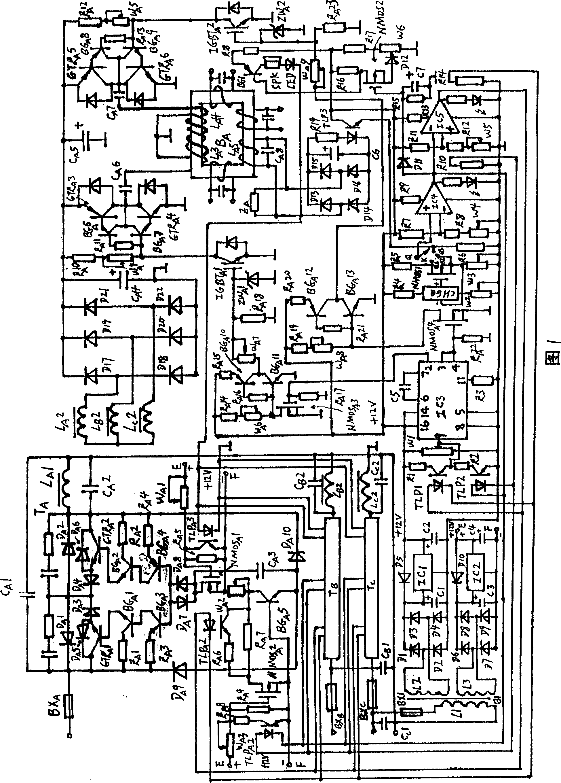
[0018] The present invention consists of a triode voltage regulating circuit T A , A phase switching signal amplifier circuit (FXKGXHFDDL), A phase switch power supply circuit (FXKGDYDL), A phase transformer load circuit, load voltage sampling circuit (FZQYDL), load environment change voltage sampling circuit (HJQYDL), sampling signal amplifier circuit (QYXHFDDL), sampling signal control circuit (QYXHKZDL), power protection start control signal generation circuit, A-phase transformer rectifier filter circuit (ZLLBDL), inverting switch signal generation circuit, auxiliary power circuit (FZDYDL) and independent power circuit (DLDYDL) composition.
[0019] Triode voltage regulator circuit T A By A-phase fuse BX A , Phase A 24th, 25th transistor GTR A 1. GTR A 2. Phase A 1--5 transistor BG A 1--BG A 5. A-phase 1st ...
Embodiment 2
[0034] Example 2: Single-phase adjustable frequency-stabilized voltage-stabilized variable-frequency variable-voltage power supply (take A-phase as an example)
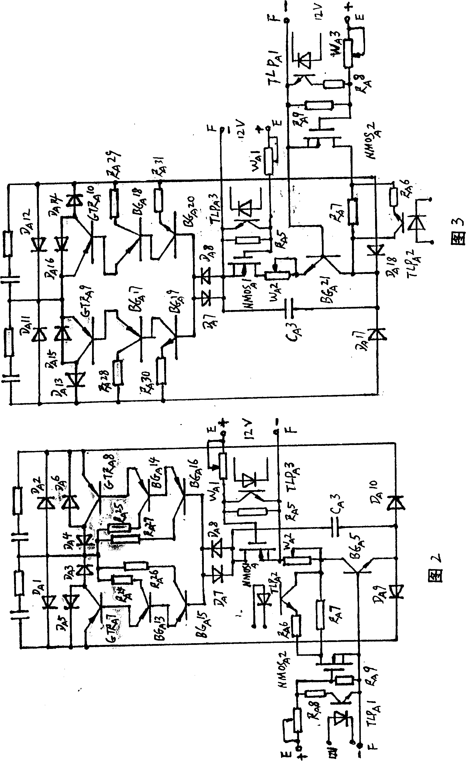
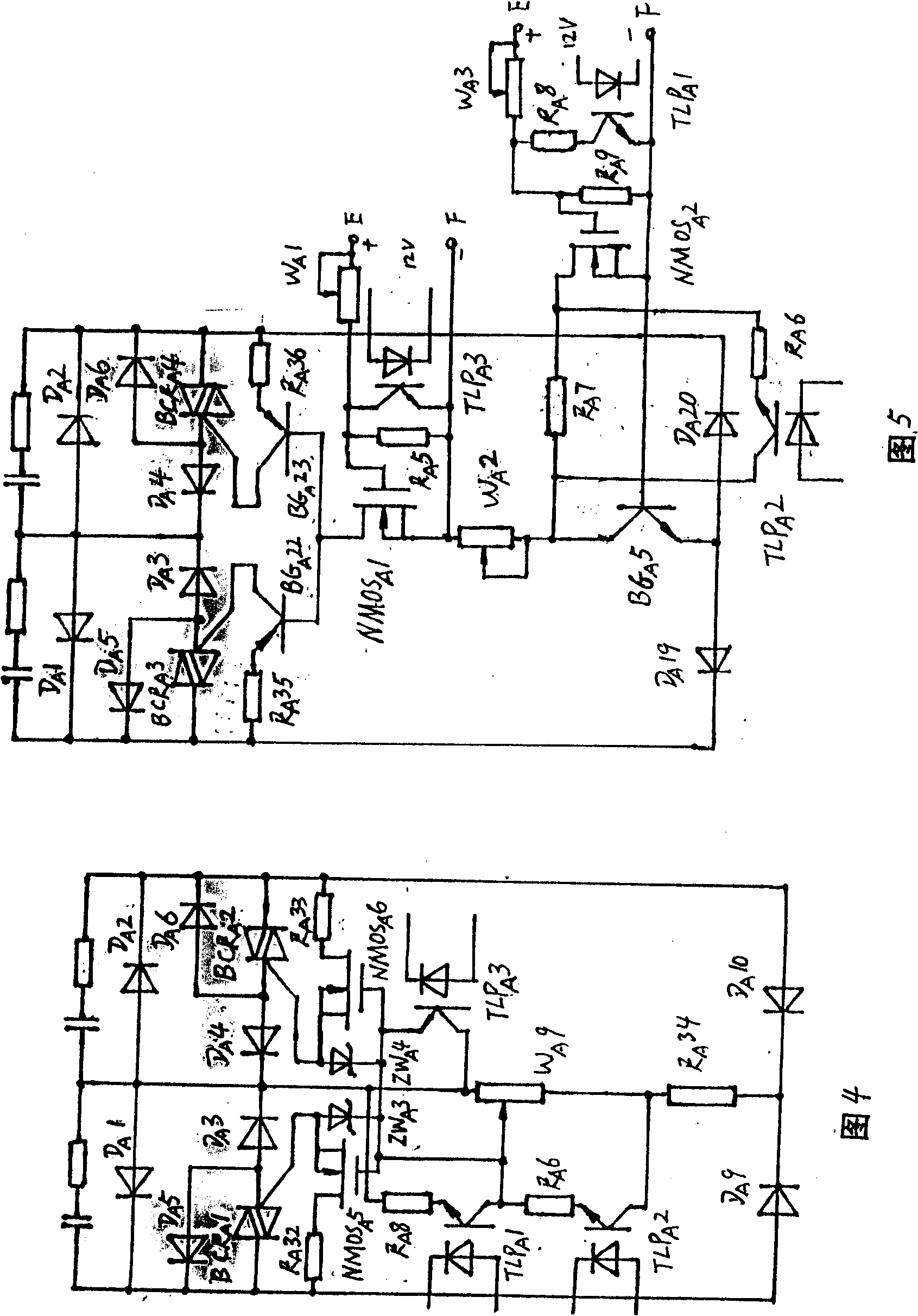
[0035] The circuit of the second embodiment is the same as the circuit of the first embodiment, the difference is: the triode voltage regulating circuit T A Replace with the first alternative circuit (see Figure 2).
[0036] Triode voltage regulator circuit T A By A-phase fuse BX A , Phase A 30th, 31st transistor GTR A 7. GTR A 8. Phase A 13-16 transistor BG A 13--BG A 16. A-phase 1st and 2nd field effect transistor NMOS A 1. NMOS A 2. A-phase 1--10 diode D A 1-D A 10. A-phase 1--3 adjustable resistance W A 1--W A 3. The 5th--9th resistor R of phase A A 5-R A 9. A-phase 24-27th resistor R A 24-R A 27. A phase 1--3 capacitor C A 1--C A 3 and other components, A-phase 30th transistor GTR A 7's emitter with A-phase fuse BX A After connecting in series, connect one end of the 380V mains, A-phase 30th tr...
Embodiment 3
[0037] Example 3: Single-phase adjustable frequency-stabilized voltage-stabilized variable-frequency variable-voltage power supply (take A-phase as an example)
[0038] The circuit of Embodiment 3 is the same as the circuit of Embodiment 1, the difference is: the triode voltage regulating circuit T A A second alternative circuit is used instead (see Figure 3).
[0039] Triode voltage regulator circuit T A By A-phase fuse BX A , A phase 32, 33 triode GTR A 9. GTR A 10. Phase A 17-21 transistor BG A 17--BG A 21. A-phase 1st and 2nd field effect transistor NMOS A 1. NMOS A 2. A-phase 7th and 8th diode D A 7. D A 8. A-phase 11-18 diode D A 11--D A 18. A-phase 1--3 adjustable resistance WA 1--W A 3. The 5th--9th resistor R of phase A A 5-R A 9. A phase 28-31 resistor R A 28-R A 31. A-phase 1--3 capacitor C A 1--C A 3 and other components, A-phase 11th diode D A 11 Anode and A phase 13 Diode D A 13 Common terminal of cathode and A-phase fuse BX A After connectin...
PUM
 Abstract
Description
Claims
Application Information
 - R&D
- Intellectual Property
- Life Sciences
- Materials
- Tech Scout
- Unparalleled Data Quality
- Higher Quality Content
- 60% Fewer Hallucinations
Browse by: Latest US Patents, China's latest patents, Technical Efficacy Thesaurus, Application Domain, Technology Topic, Popular Technical Reports.
© 2025 PatSnap. All rights reserved.Legal|Privacy policy|Modern Slavery Act Transparency Statement|Sitemap|About US| Contact US: help@patsnap.com


