An ultra-short pulse laser scan device

A technology of ultra-short pulse laser and scanning device, which is applied in optics, optical components, nonlinear optics, etc., can solve the problems of complex optical path design, improve focusing quality, improve multi-photon excitation efficiency, and facilitate wide-scale application Effect

Inactive Publication Date: 2009-02-04
HUAZHONG UNIV OF SCI & TECH
View PDF7 Cites 1 Cited by
  • Summary
  • Abstract
  • Description
  • Claims
  • Application Information

AI Technical Summary

Problems solved by technology

The design of the optical path in this way is more complicated

Method used


Image

  • An ultra-short pulse laser scan device
  • An ultra-short pulse laser scan device
  • An ultra-short pulse laser scan device

Examples


example 1

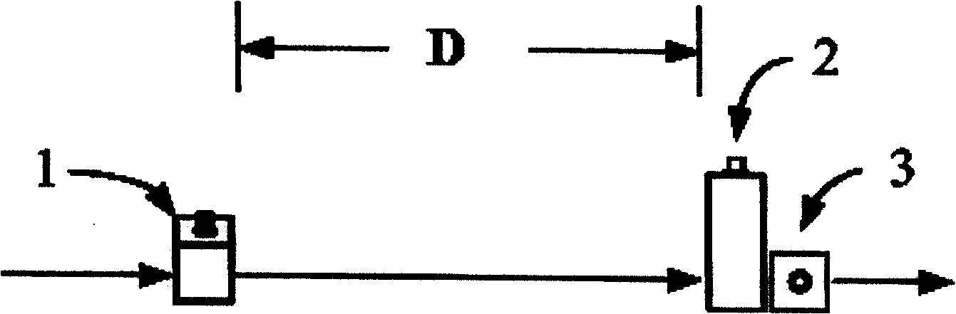
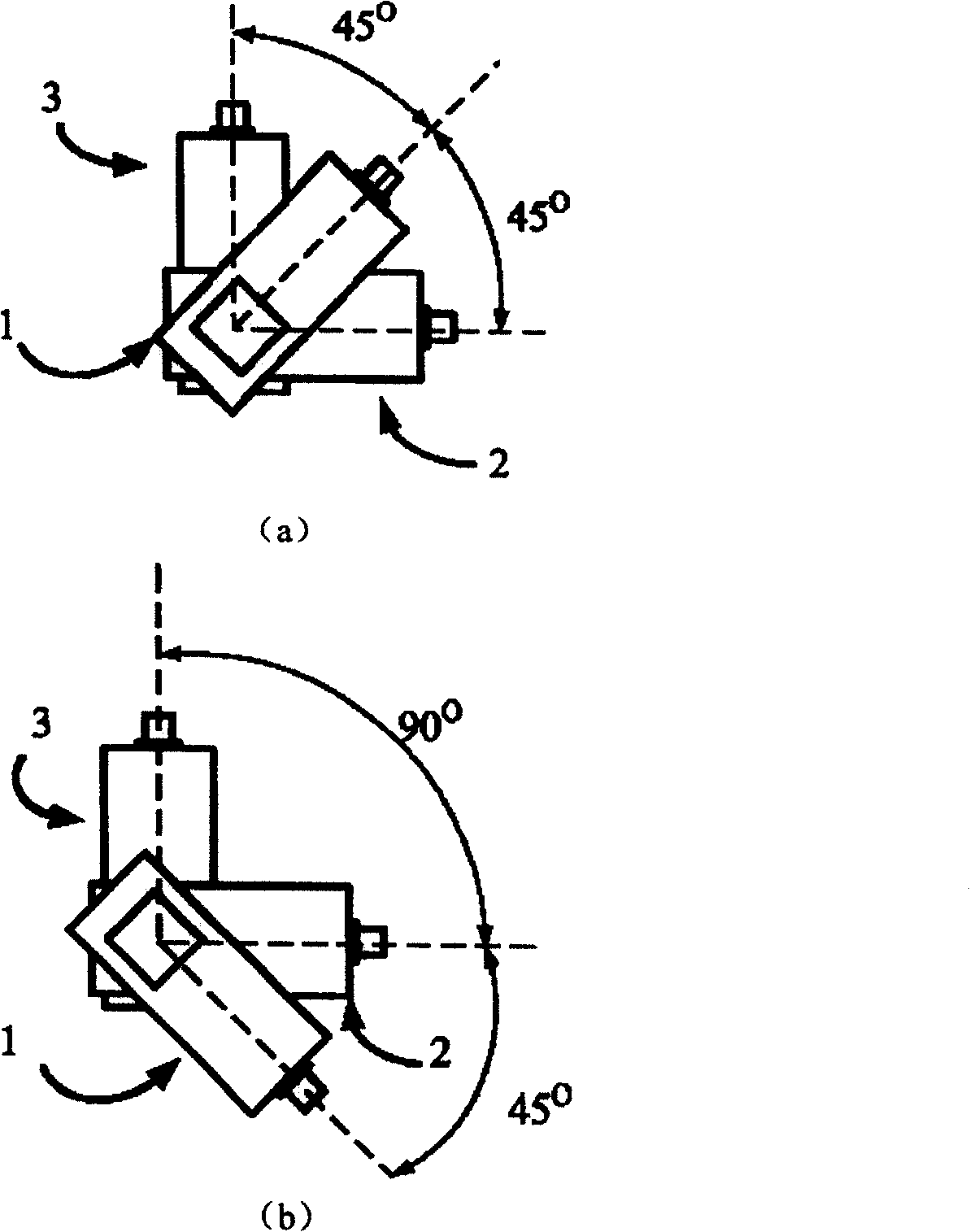
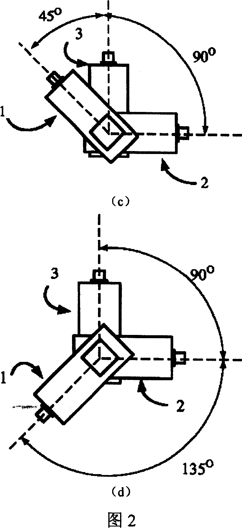
[0035] Such as image 3 Build the test light path. Laser 4 incident laser light (center wavelength 800 nanometers, bandwidth 10 nanometers, initial pulse width 120 femtoseconds) passes through the acousto-optic modulator 1 placed obliquely at 45 degrees, and exits with negative first-order diffracted light. The modulation frequency of the acousto-optic modulator 1 135.7MHz. Since the AOD used in this experiment is sensitive to the polarization state of the incident light, a 1 / 2 wave plate 5 is arranged between the AOM 1 and the two-dimensional AOD. The laser beam passes through the 1 / 2 wave plate 5 and then goes to the two-dimensional acousto-optic deflector with a central operating frequency of 96MHz. The two-dimensional acousto-optic deflectors all use positive first-order diffracted light, the outgoing light hits the light screen 6, and the light spot on the light screen is photographed by the CCD 7 to obtain the following Figure 5 (a) The results shown. The laser beam...

example 2

[0039] The laser beam after the space and time are all compensated is guided into the microscope objective lens 8 (60 times oil lens is used in the experiment, NA=1.24), and the optical path is as follows Figure 8 shown. The dichroic mirror 9 is used to reflect the excitation light and transmit the signal light, and the PMT 10 is used for signal detection. Scan the 170nm fluorescent bead sample 11 to get the experimental picture as Figure 9 As shown in Fig. 10(a) and Fig. 10(b), the resolutions of the X and Y axes were analyzed and measured to be 374 and 385 nanometers respectively. Using PZT for Z-axis resolution measurement, the minimum Z-axis resolution is 1.1 microns, as shown in Figure 10(c).

[0040] For the AOM 1, its modulation frequency is often higher (for example, to compensate the dispersion of a two-dimensional AOD with a center operating frequency of 96 MHz, the modulation frequency of the AOM 1 needs to be loaded to 135.74 MHz). For near-infrared or infrare...


PUM


Abstract

The invention discloses an ultrashort pulse laser scanning device. It includes acoustooptic modulator and 2-D acousto-optic deflector which are at the same light path, the 2-D acousto-optic deflector is constructed with two acousto-optic deflectors, the included angle between the acousto-optic deflector and the acoustooptic modulator is 45+-5 degree. The modulating frequency of the acoustooptic modulator is fAOM=f+-10%f, the distance between the acoustooptic modulator and 2-D acousto-optic deflector is D=L+-10%L. When acousto-optic deflector is used to 2-D scan the laser, the device can compensate the spatial dispersion and temporal dispersion introduced by using acousto-optic deflector to scan ultrashort pulse laser beam. The device possesses simple structure, light path is easy to adjust, and it fits for the fields of femtosecond laser storage, imaging and laser micro-processing, specially the random scan of the laser beam.

Description

technical field [0001] The invention belongs to the technical field of laser scanning, and in particular relates to an ultrashort pulse laser scanning device with dispersion compensation function based on a two-dimensional acousto-optic deflector (AOD), which is suitable for femtosecond laser storage, imaging and laser scanning fields of micromachining. Background technique [0002] Using acousto-optic deflectors to scan laser light is a very promising laser scanning technology. It is especially suitable for the fields of femtosecond laser storage, imaging and laser microprocessing. However, when using an acousto-optic deflector to scan an ultrashort pulse laser, the laser beam will produce spatial dispersion and temporal dispersion, which will affect the excitation efficiency of multiphotons. Therefore, spatial and temporal dispersion must be compensated for when ultrashort pulses are scanned using an AOD. [0003] At present, there have been many articles and patents on...

Claims


Application Information

Patent Timeline
Patent Type & Authority Patents(China)
IPC IPC(8): G02B26/10G02F1/33G02F1/11
Inventor 骆清铭曾绍群毕昆吕晓华薛松超吴萍
Owner HUAZHONG UNIV OF SCI & TECH
Why Eureka
Try Eureka