
Photothermal effect measurement system and method of strong scattering material

A photothermal effect and measurement system technology, which is applied in the direction of measuring devices, analyzing materials, and material analysis through optical means, can solve the problems of weak infrared radiation signals, opaque strong scattering materials, and weak light absorption ability, etc., and achieve good gain , Improve the absorption effect, the effect of a wide range of applications

Inactive Publication Date: 2018-11-06
UNIV OF ELECTRONICS SCI & TECH OF CHINA
View PDF8 Cites 1 Cited by
  • Summary
  • Abstract
  • Description
  • Claims
  • Application Information

AI Technical Summary

Problems solved by technology

[0008] The purpose of the present invention is: in order to solve the problem that the existing photothermal effect measurement system measures the radiation characteristics of strong scattering materials, due to the characteristics of opaque and high scattering of strong scattering materials, the light absorption ability is not strong, resulting in weak infrared radiation signals and low collection efficiency , a problem that is difficult to detect, the present invention provides a photothermal effect measurement system of strong scattering materials and its measurement method

Method used


Image

  • Photothermal effect measurement system and method of strong scattering material
  • Photothermal effect measurement system and method of strong scattering material

Examples


Embodiment 1

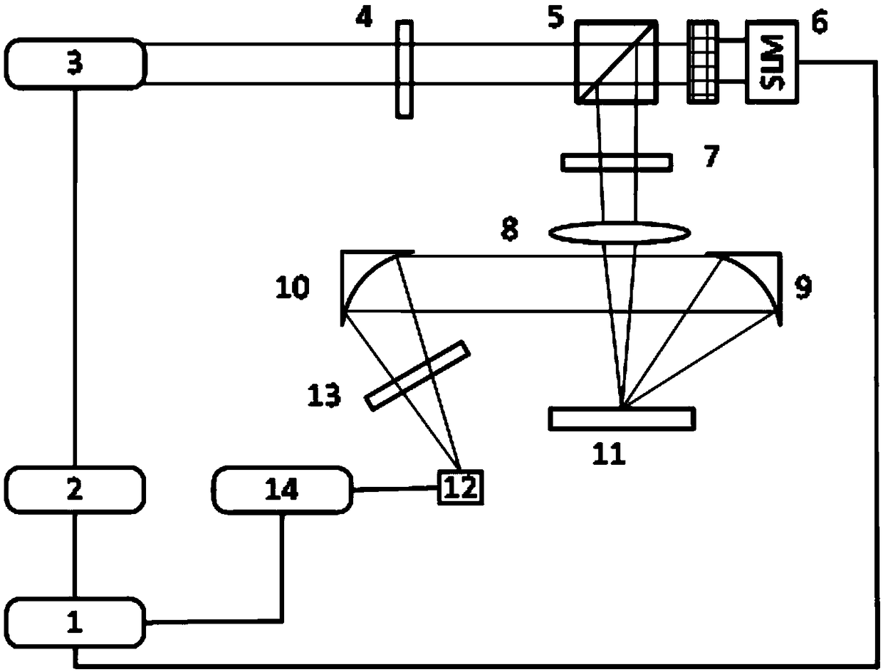
[0043] Such as figure 1 As shown, this embodiment provides a photothermal effect measurement system for strong scattering materials, including a computer 1, a function signal generator 2, a laser 3, a test platform 11 for placing the material to be tested, a light-concentrating component, and a computer 1 For the signal feedback component connected, the computer 1 is connected to the function signal generator 2 through a data line, and the reference signal output end of the function signal generator 2 is electrically connected to the laser 3 through a laser control line. It also includes an optical path converter 5 and a spatial light modulator. SLM6. In this embodiment, the laser 3 selects a semiconductor laser with a wavelength of 785nm, the optical path converter 5 selects a 50% non-polarized beam splitting BS mirror, and the spatial light modulator SLM6 selects a reflective spatial light modulator SLM corresponding to the optical path converter. 5 is set at the same level as...

Embodiment 2

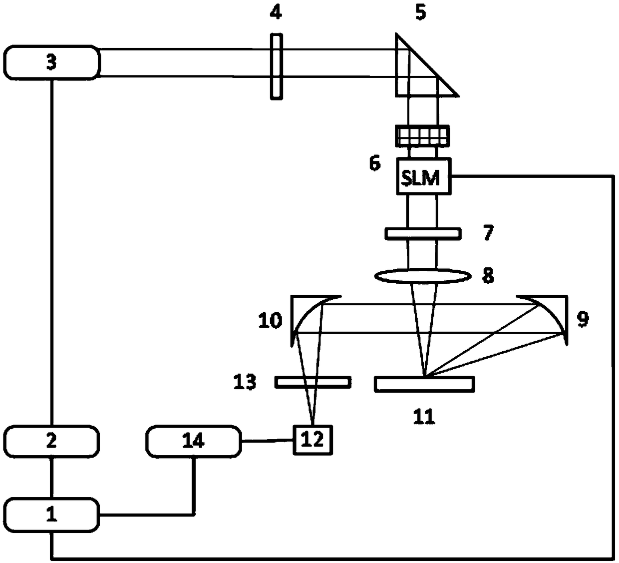
[0058] Such as figure 2 As shown, this embodiment provides a photothermal effect measurement system for strong scattering materials, including a computer 1, a function signal generator 2, a laser 3, a test platform 11 for placing the material to be tested, a light-concentrating component, and a computer 1 For the signal feedback component connected, the computer 1 is connected to the function signal generator 2 through a data line, and the reference signal output end of the function signal generator 2 is electrically connected to the laser 3 through a laser control line. It also includes an optical path converter 5 and a spatial light modulator. SLM6. In this embodiment, the laser 3 selects a semiconductor laser with a wavelength of 785nm, the optical path converter 5 selects a right-angle prism, and the spatial light modulator SLM6 selects a transmissive spatial light modulator SLM correspondingly. The spatial light modulator SLM6 is set in the optical path conversion Directl...


PUM


Abstract

The invention discloses a photothermal effect measurement system and method of a strong scattering material and relates to the technical field of non-destructive testing of materials. The system comprises a computer, a function signal generator, a laser, a testing platform for storing a to-be-tested material, a condensation module, a signal feedback module electrically connected with the computer,a light path converter and an SLM (spatial light modulator), wherein the light path converter and the laser are arranged at the same horizontal height, the SLM is electrically connected with the computer, the testing platform is arranged right below the light path converter, the condensation module is used for gathering modulated laser, a sample has temperature rise and fall and infrared radiation under the photothermal effect after the laser irradiates the sample, and radiation signals produced by the to-be-tested material are collected and reflected to the signal feedback module. The SLM isused for performing wavefront regulation and compensating the scattering phase, so that the absorption effect is improved, strong scattering in material characteristic measurement is reduced, and infrared radiation signals on the surface of the material are enhanced.

Description

Technical field [0001] The invention relates to the technical field of material non-destructive testing, and more specifically to a photothermal effect measurement system and a measurement method for strong scattering materials. Background technique [0002] The photothermal radiation characteristic is an important characteristic parameter of the material. It has important application value in the fields of atmospheric remote sensing, target characteristic research, biomedical optical imaging, laser non-destructive inspection, etc. Therefore, the experimental method of measuring the photothermal radiation of the material is suitable for the above-mentioned materials. The research in the application field is of great significance. [0003] As a non-contact, non-invasive and non-destructive technology, the general process of the photothermal radiation measurement (Photothermalradiometry, PTR) principle can be understood as: the intensity-modulated laser beam is concentrated and irrad...

Claims


Application Information

Patent Timeline
Patent Type & Authority Applications(China)
IPC IPC(8): G01N21/17
CPCG01N21/171
Inventor 成祎珊张希仁杨立峰彭真明冉啟锐
Owner UNIV OF ELECTRONICS SCI & TECH OF CHINA
Learn More