Environmental protection, energy sources recovery type garbage treatment equipment

A technology of waste treatment device and energy recovery, applied in the direction of combustion type, combustion method, lighting and heating equipment, etc., can solve the problems of long construction period, large landfill occupation, polluted groundwater, etc., to reduce investment and operation costs, The effect of large biomass reduction and complete gasification and combustion

Inactive Publication Date: 2009-01-07
SHENZHEN JUNENG BIOMASS GASIFICATION TECH
View PDF8 Cites 0 Cited by
  • Summary
  • Abstract
  • Description
  • Claims
  • Application Information

AI Technical Summary

Problems solved by technology

The existing waste treatment technology is landfill, accounting for 85%, composting 10%, and incineration 3-5%, but these three treatment methods all have shortcomings: landfill occupies a large area, releases harmful gases, pollutes groundwater, brings Secondary pollution; compost sorting process is complex, high cost, low fertilizer efficiency, no market for compost products; low incineration temperature, easy to form dioxin-like toxic substances, causing secondary pollution, and huge investment, long construction period, operation and maintenance costs high, difficult to maintain

Method used


Image

  • Environmental protection, energy sources recovery type garbage treatment equipment
  • Environmental protection, energy sources recovery type garbage treatment equipment
  • Environmental protection, energy sources recovery type garbage treatment equipment

Examples


Embodiment 1

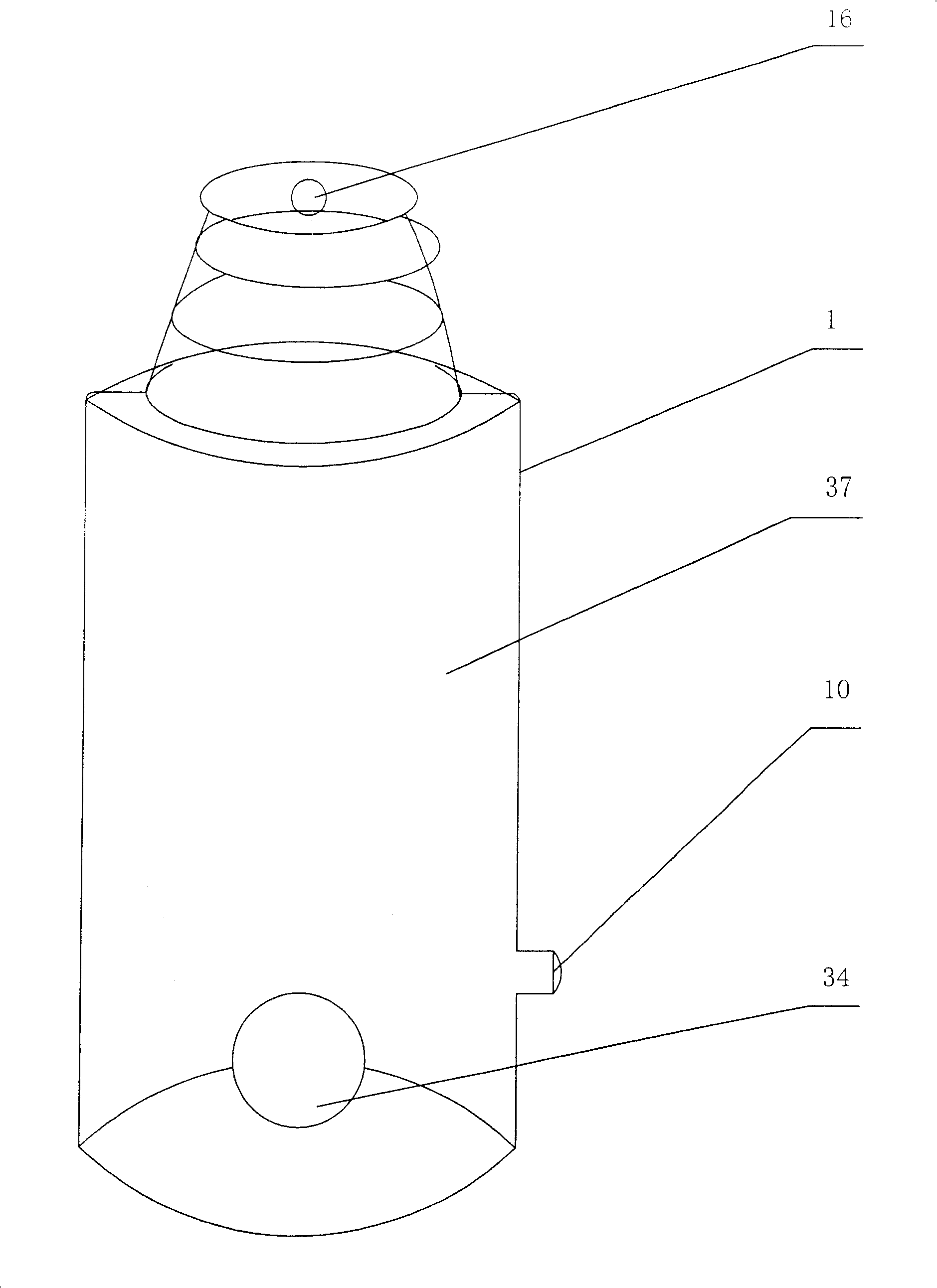
[0038] Such as image 3 As shown, it is a perspective view of the furnace body. The feed inlet 16 is arranged at the top of the furnace body 1 , the furnace 37 is in the furnace body 1 , the slag outlet 34 is arranged at the bottom of the furnace body 1 , and the furnace door 10 is arranged on the furnace body 1 .

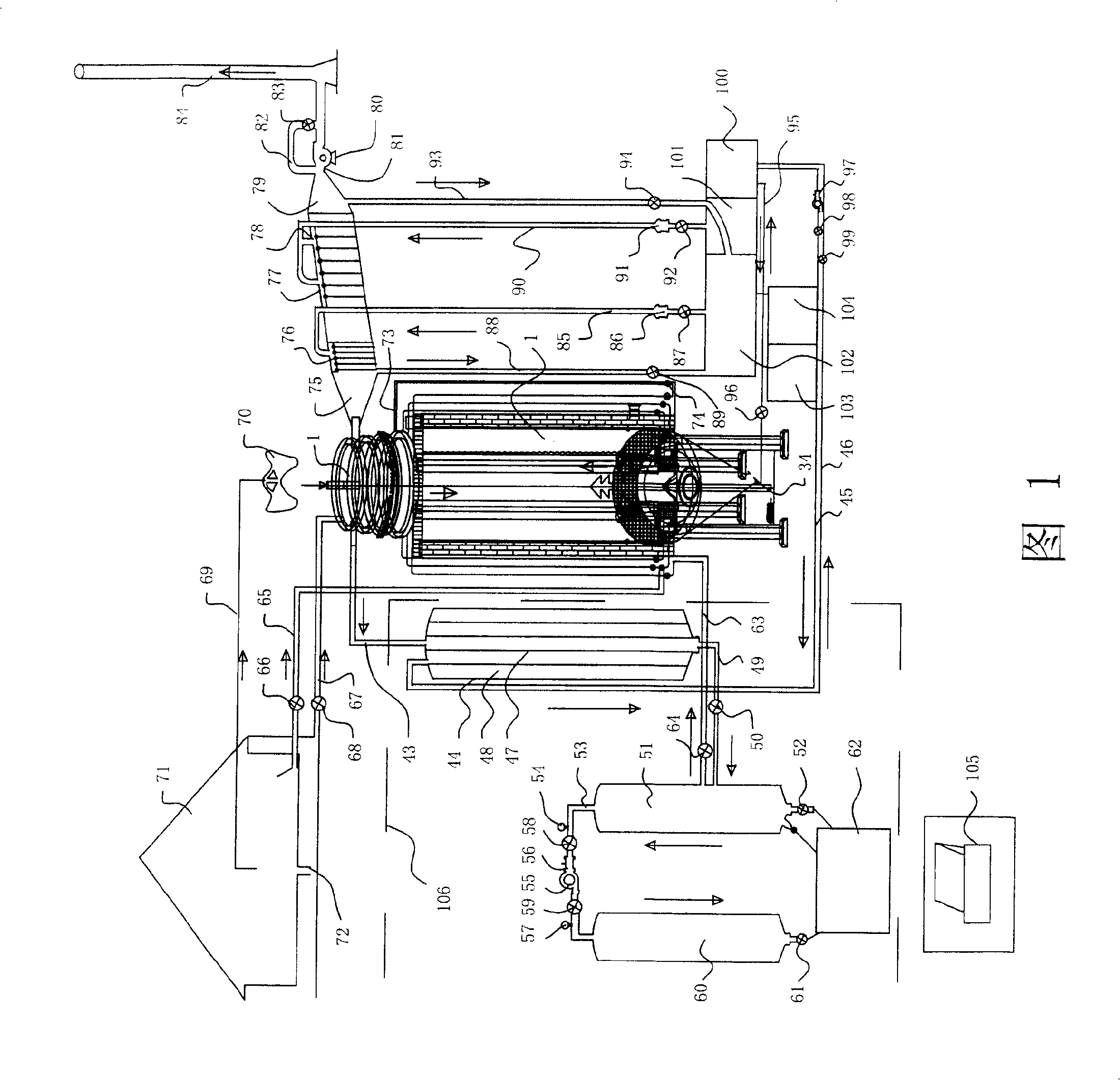
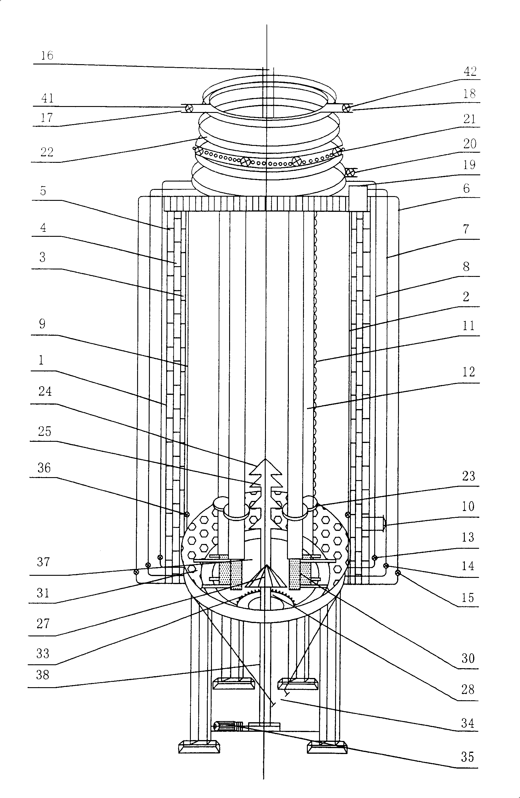
[0039] As shown in Figures 1 and 2, they are respectively the structural schematic diagram of the environmental protection and energy recovery type garbage treatment device and the furnace body structural schematic diagram of the present invention. An environment-friendly, energy-recovery garbage treatment device, comprising a furnace body 1, the top of the furnace body 1 is provided with a feed port 16 and the bottom is provided with a slag outlet 34, the furnace body 1 is connected to a gas recovery device 106, a smoke The gas purification device 75, the present technical proposal also includes the spiral smoke box 22 arranged on the upper part of the furnace bo...

Embodiment 2

[0062] The difference between this embodiment and the first embodiment is that there are twelve secondary combustion fire tubes 12 in this embodiment, and the effects achieved by this embodiment and the first embodiment remain the same.


PUM


Abstract

A garbage processing device of energy recovery type consists of furnace; fuel has recovering unit and smoke purification unit. It is featured as forming fuel gas recovering unit by condenser, oil-gas separator, air cabinet, oil storage pool; connecting condenser to fuel gas port and oil-gas separator; setting spray quencher and sprayer in smoke purification unit, arranging smoke buffer box at tail end of smoke purification unit and connecting said box to chimney through draught fan.

Description

technical field [0001] The invention relates to a waste treatment device, in particular to an environment-friendly and energy-recovery type garbage treatment device which recycles various garbage wastes after treatment and the generated waste gas has been purified. Background technique [0002] Biomass energy refers to various organisms produced by photosynthesis. Bioenergy is an energy form in which solar energy is stored in organisms in the form of chemical energy, and it is an energy that uses biomass as a carrier. Biomass gasification refers to the use of combustible gases produced by anoxic combustion of plant stems, branches, leaves, straw, chaff, industrial and agricultural and urban solid organic waste, etc., for various purposes. [0003] The biomass resources in the world are huge in quantity and in various forms, such as firewood, agricultural and forestry crops, agricultural and forestry residues, leftovers from food processing and forest product processing, and ...

Claims


Application Information

Patent Timeline
Patent Type & Authority Patents(China)
IPC IPC(8): F23G5/027F23J15/04
CPCF23G5/027F23J15/02
Inventor 王玉志徐淑萍
Owner SHENZHEN JUNENG BIOMASS GASIFICATION TECH
Why Eureka
Try Eureka