
Oxide cathode for electron gun with a differentially doped metallic substrate

A technology of oxide cathode and metal substrate, applied in the direction of discharge tube solid thermionic cathode, discharge tube main electrode, circuit, etc., can solve the problem of good operation and harmfulness, and achieve the effect of optimizing the on-time

Inactive Publication Date: 2008-11-26
THOMSON LICENSING SA
View PDF5 Cites 0 Cited by
  • Summary
  • Abstract
  • Description
  • Claims
  • Application Information

AI Technical Summary

Problems solved by technology

The deposition of metal vapors of reducing elements from the cathode on these electrical connectors creates leakage or open circuits between the gun electrodes, which is detrimental to the good operation of the electron gun in cathode ray tubes

Method used


Image

  • Oxide cathode for electron gun with a differentially doped metallic substrate
  • Oxide cathode for electron gun with a differentially doped metallic substrate
  • Oxide cathode for electron gun with a differentially doped metallic substrate

Examples


Embodiment Construction

[0069] In order to simplify the description and to demonstrate the differences and advantages of the present invention over the prior art, the same reference symbols will be used to denote elements providing the same functions.

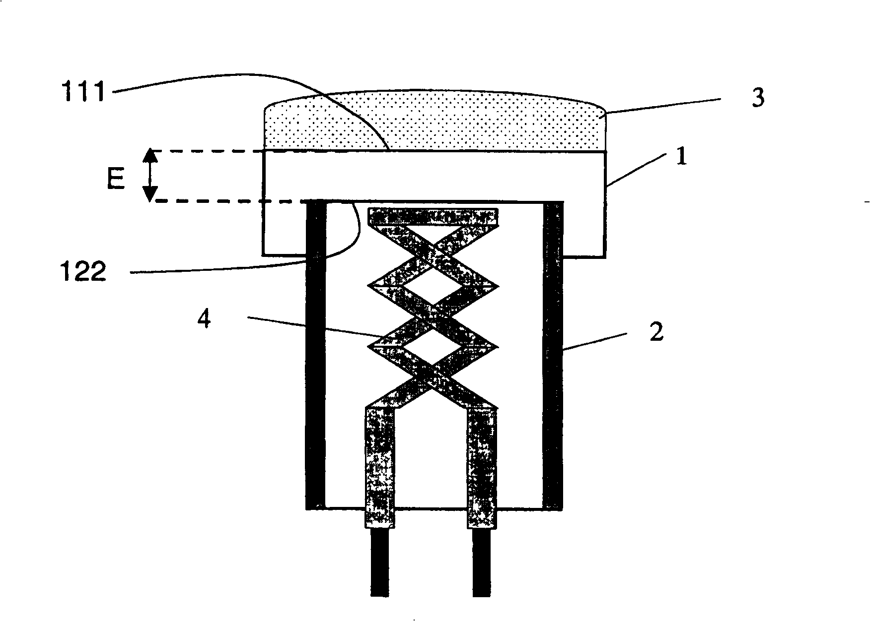
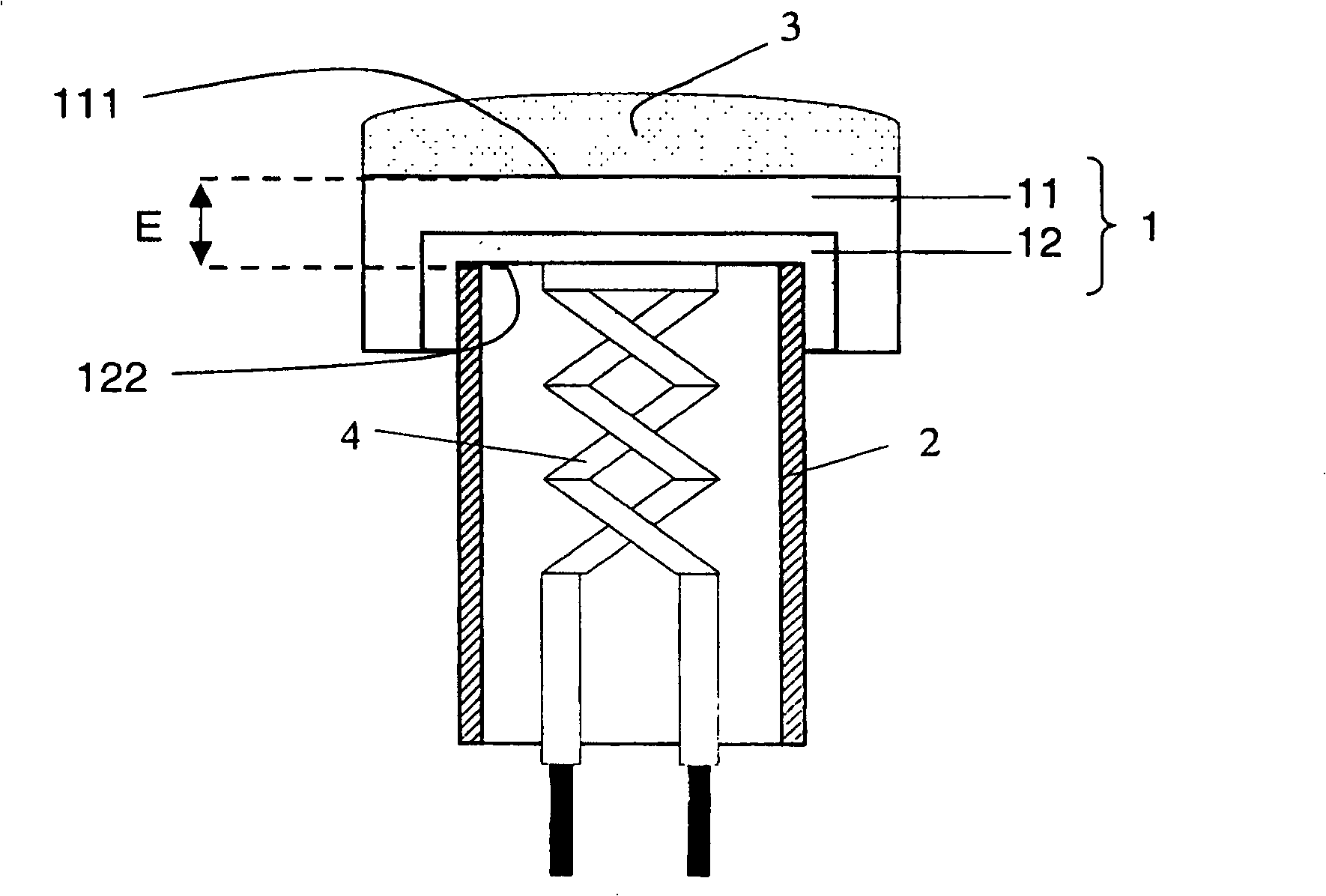
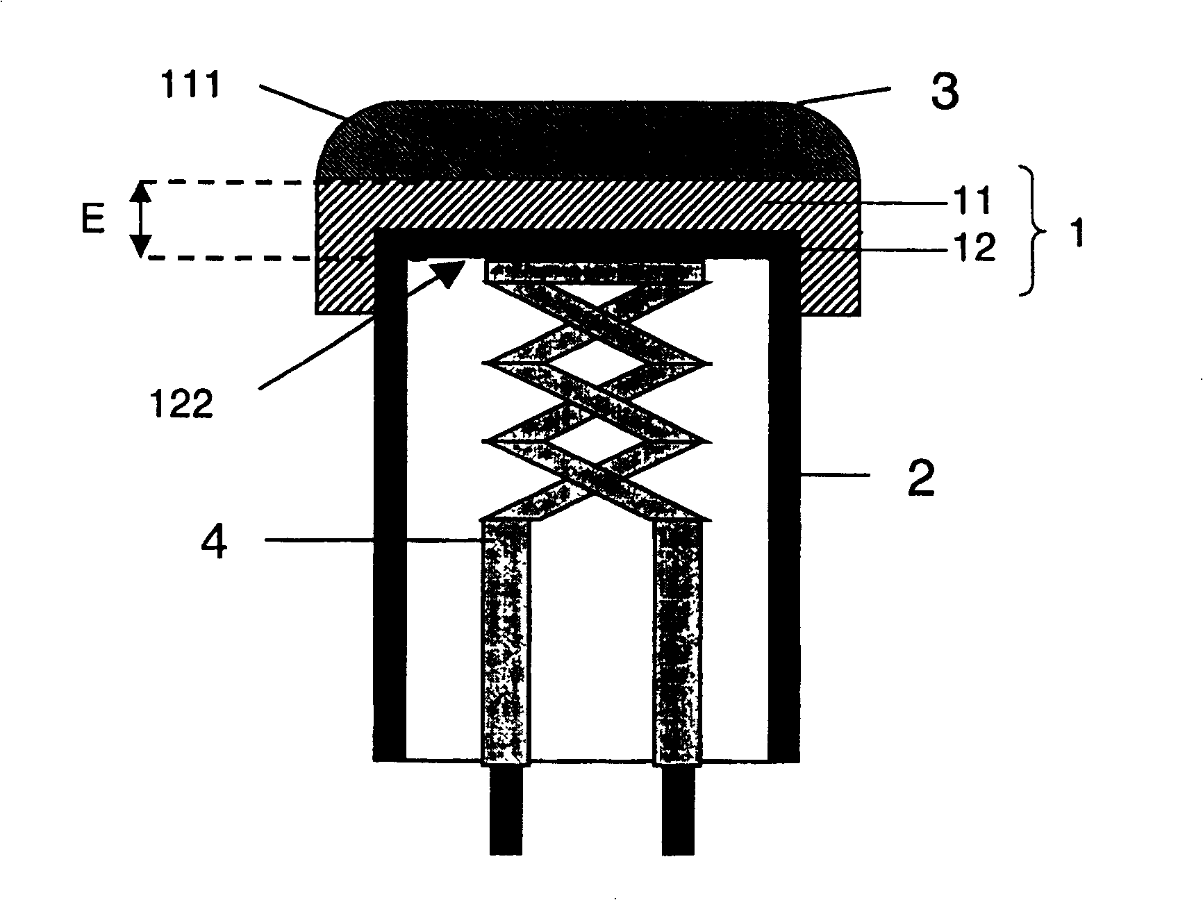
[0070] Now, we will use the main components described for such as image 3 The bimetallic substrate 1 of the one-piece cathode is shown to describe the invention. As any bimetal, this bimetal consists of two superimposed connected layers, a top layer 11 with a top surface 111 in contact with the cathode emitter layer 3 and a bottom layer with its outer bottom surface 122 facing the heater 4 inside the casing 2 .

[0071] The top layer consists mainly of nickel; its thickness is approximately 60 μm.

[0072] The bottom layer consists mainly of a nickel alloy with 20% chromium, known as nichrome; its thickness is approximately 30 μm.

[0073] The substrate 1 according to the invention is made of a 70-100 μm thick bimetal; even if the W concentration i...


PUM

PropertyMeasurementUnit
thicknessaaaaaaaaaa
thicknessaaaaaaaaaa
thicknessaaaaaaaaaa

Abstract

The metallic substrate of this cathode has a thickness <= 100 mu m and contains a plurality of reducing agents as Si or Al and : on the top face 111, 0.005 % < Mg <= 0.1 %, Si or Al <= 0.025 %, and W <= 3 %, on the bottom face 122, Mg weight concentration is inferior to the Mg weight concentration on the top face, and Si or Al weight concentration is superior to Si or Al weight concentration on the top face and superior to 0.02 %. Lifetime is maximized and turn-on-time is minimized.

Description

technical field [0001] The present invention relates to an oxide cathode as a source of electrons which is commonly used in an electron gun of a cathode ray tube. Electrons are emitted from the cathode due to the thermionic effect. Cathode ray tubes are primarily used as display devices for computers or televisions. Background technique [0002] refer to figure 1 , conventional oxide cathodes include [0003] - a cathode emissive layer 3 consisting essentially of an alkaline earth metal oxide or a mixture of these oxides; [0004] - The substrate 1 on which the cathode emitter layer 3 is arranged, usually made of a nickel alloy containing one or several reducing agents such as Mg, Al, Si, W, Cr and / or Zr. The nickel alloy of the substrate 1 is generally based on a mixture of nickel and tungsten or a mixture of nickel and molybdenum. [0005] More precisely, as figure 1 The conventional oxide cathode shown comprises a cup-shaped nickel alloy single-layer substrate 1, a ...

Claims


Application Information

Patent Timeline
Patent Type & Authority Patents(China)
IPC IPC(8): H01J1/142H01J1/26H01J1/14H01J1/20H01J29/48
CPCH01J1/26
Inventor 让-迈克尔·龙奎斯唐纳德·约翰·维尔斯克
Owner THOMSON LICENSING SA
Learn More