Process cartridge and image forming apparatus
A technology for processing cartridges and images, which is applied in the direction of electric recording process applying charge pattern, equipment of electric recording process applying charge pattern, electric recording technique, etc., to achieve the effect of suppressing deflection, improving position accuracy and reducing deviation
- Summary
- Abstract
- Description
- Claims
- Application Information
AI Technical Summary
Problems solved by technology
Method used
Image

Examples
no. 1 example
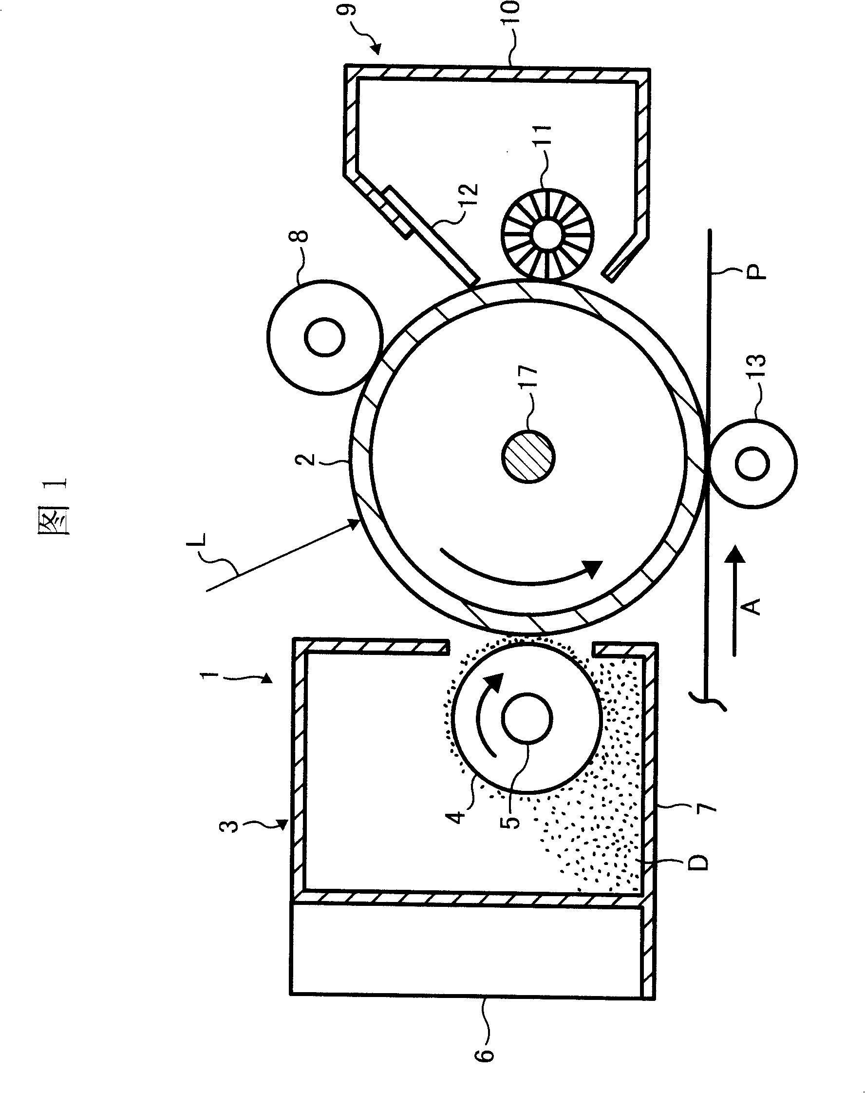
[0108] FIG. 1 is a schematic vertical sectional view of a process cartridge and other processing equipment installed at a predetermined position within the main body of an image forming apparatus. The process cartridge 1 shown here is provided with an image carrier 2 made of a drum-shaped photoreceptor and a developing unit 3 as an example of a rotary unit, and the image carrier 2 and the developing unit 3 are detachably connected to form a integration. The developing unit 3 is provided with a developing roller 4 and a unit body 6. The developing roller 4 is arranged as an example of a rotating body to face the image carrier 2. The unit body 6 supports the shaft 5 of the developing roller 4 so that It can be swiveled. The shaft 5 can be integrally formed with the developing roller 4 or connected integrally with the developing roller 4 . The unit body 6 is provided with a developing casing 7 in which dry developer D is accommodated, and the developing roller 4 is arranged in ...
no. 2 example
[0138] The second embodiment is also described with reference to FIG. 1. When forming an image, the image carrier 2 is driven to turn counterclockwise as shown in FIG. The polarity is charged, and the writing light L is emitted from an exposure device (not shown) to irradiate the charged surface of the image carrier 2, so that an electrostatic latent image is formed on the image carrier 2.
[0139] On the other hand, the developing roller 4 that drives the developing unit 3 rotates clockwise as shown in FIG. The electrostatic latent image on the body 2 is developed and visualized as a toner image.
[0140] The transfer material P is supplied from a paper feeding device (not shown), and is transported in the arrow A direction. The toner image is transferred onto the transfer material P by the action of the transfer roller 13 . After the transfer material P is detached from the image carrier 2, the toner image is fixed on the transfer material P through a fixing device (not sh...
no. 3 example
[0181] 16 is a right side view showing a schematic internal structure of a color printer 101 as an electrophotographic image forming apparatus according to a third embodiment of the present invention. An image forming unit 103 , an optical writing unit 104 , a paper feed cassette 105 , a fixing device 106 , and the like are housed in an apparatus main body 102 of the color printer 101 .
[0182] The image forming section 103 is constituted by four image forming sections 107Y, 107M, 107C, 107K, an intermediate transfer unit 108 located below the image forming sections 107, a secondary transfer bias roller 109, and the like. Y, M, C, and K in the symbols represent yellow, magenta, cyan, and black, respectively.
[0183] The four image forming units 107Y, 107M, 107C, and 107K form toner images of different colors. The four image forming sections 107Y, 107M, 107C, and 107K have the same structure, and each consists of a photoreceptor assembly 110, and a charging roller 111 arrang...
PUM
 Abstract
Description
Claims
Application Information
 - R&D
- Intellectual Property
- Life Sciences
- Materials
- Tech Scout
- Unparalleled Data Quality
- Higher Quality Content
- 60% Fewer Hallucinations
Browse by: Latest US Patents, China's latest patents, Technical Efficacy Thesaurus, Application Domain, Technology Topic, Popular Technical Reports.
© 2025 PatSnap. All rights reserved.Legal|Privacy policy|Modern Slavery Act Transparency Statement|Sitemap|About US| Contact US: help@patsnap.com