


Quick Research
Generate reliable direction feasibility study reports for your R&D in just a few steps.

Technical Q&A
Discover and master advanced knowledge NOW. Basics, ideas, possibilities, all at once.

Find Solutions
As an expert in R&D theories, this can generate solutions to your technical problems instantly.

Evaluate Feasibility
Analyze your overall solution with one click, know your potential R&D risks in advance.

Monitor Landscape
Get weekly tech updates, stay abreast of the latest tech innovations and key insights.
Process cartridge and image forming apparatus
A technology for processing cartridges and images, applied to electrical recording technology using charge graphics, equipment using electrical recording technology using charge graphics, and electrical recording techniques, to achieve the effects of improving positional accuracy, suppressing deflection, and reducing deviations
- Summary
- Abstract
- Description
- Claims
- Application Information
AI Technical Summary
Problems solved by technology
Method used
Image

Examples
no. 1 example
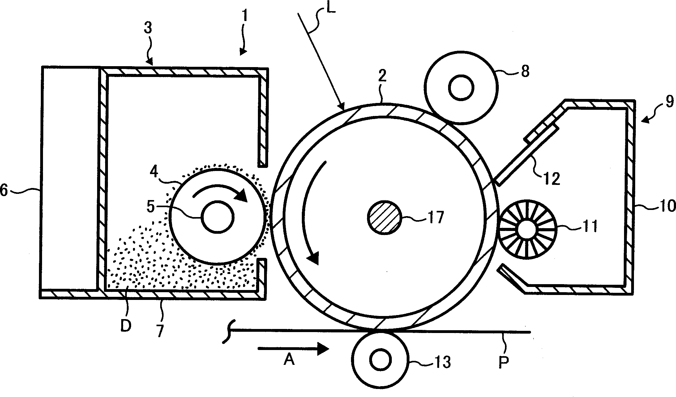
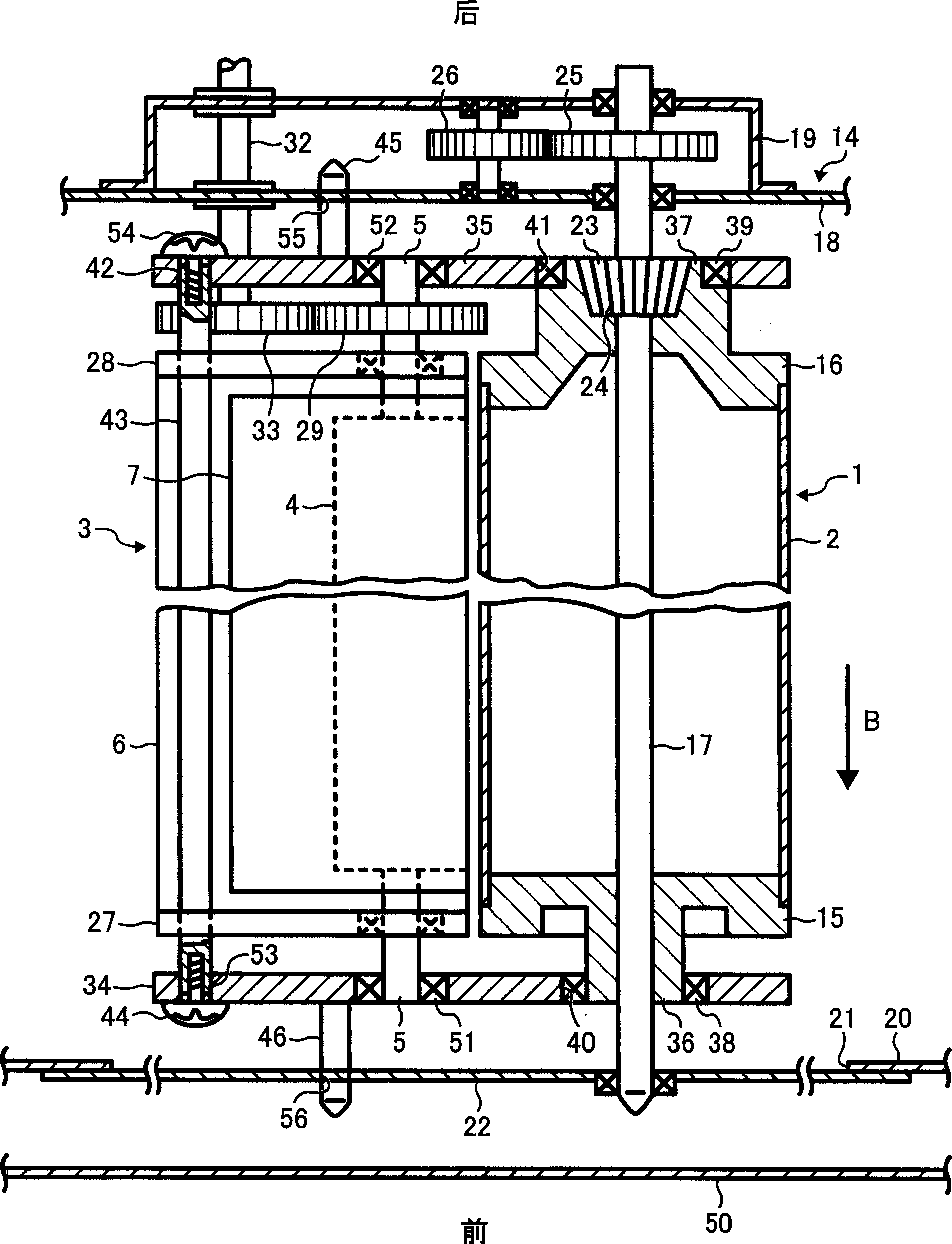
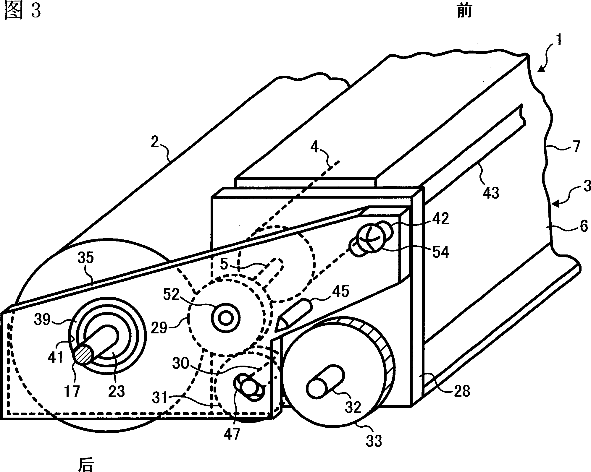
[0108] figure 1 It is a schematic vertical cross-sectional view of a process cartridge and other processing equipment installed at predetermined positions in the main body of the image forming apparatus. The process cartridge 1 shown here is provided with an image carrier 2 made of a drum-shaped photoreceptor and a developing unit 3 as an example of a rotary unit, and the image carrier 2 and the developing unit 3 are detachably connected to form a integration. The developing unit 3 is provided with a developing roller 4 and a unit body 6. The developing roller 4 is arranged as an example of a rotating body to face the image carrier 2. The unit body 6 supports the shaft 5 of the developing roller 4 so that It can be swiveled. The shaft 5 can be integrally formed with the developing roller 4 or connected integrally with the developing roller 4 . The unit body 6 is provided with a developing casing 7 in which dry developer D is accommodated, and the developing roller 4 is arra...
no. 2 example
[0138] The second embodiment also refers to figure 1 To illustrate, when forming an image, the image carrier 2 is driven toward figure 1 At this time, the image carrier 2 is charged with the set polarity by the charging roller 8, and the writing light L is emitted from the exposure device (not shown) to irradiate the image carrier 2. In this way, an electrostatic latent image is formed on the image carrier 2 .
[0139] On the other hand, the developing roller 4 of the developing assembly 3 is driven toward figure 1 As shown, it rotates clockwise. At this time, the developer D is placed and conveyed on the peripheral surface of the developing roller 4, and the electrostatic latent image formed on the image carrier 2 is developed by the developer and visualized. , becomes a toner image.
[0140] The transfer material P is supplied from a paper feeding device (not shown), and is transported in the arrow A direction. The toner image is transferred onto the transfer material P ...
no. 3 example
[0181] Figure 16 It is a right side view showing a schematic internal structure of a color printer 101 as an electrophotographic image forming apparatus according to a third embodiment of the present invention. An image forming unit 103 , an optical writing unit 104 , a paper feed cassette 105 , a fixing device 106 , and the like are housed in an apparatus main body 102 of the color printer 101 .
[0182] The image forming section 103 is constituted by four image forming sections 107Y, 107M, 107C, 107K, an intermediate transfer unit 108 located below the image forming sections 107, a secondary transfer bias roller 109, and the like. Y, M, C, and K in the symbols represent yellow, magenta, cyan, and black, respectively.
[0183] The four image forming units 107Y, 107M, 107C, and 107K form toner images of different colors. The four image forming sections 107Y, 107M, 107C, and 107K have the same structure, and each consists of a photoreceptor assembly 110, and a charging rolle...
PUM
 Abstract
Description
Claims
Application Information
 - R&D Engineer
- R&D Manager
- IP Professional
- Industry Leading Data Capabilities
- Powerful AI technology
- Patent DNA Extraction
Browse by: Latest US Patents, China's latest patents, Technical Efficacy Thesaurus, Application Domain, Technology Topic, Popular Technical Reports.
© 2024 PatSnap. All rights reserved.Legal|Privacy policy|Modern Slavery Act Transparency Statement|Sitemap|About US| Contact US: help@patsnap.com