Drawing force controllable manual hydraulic drawing tool

A controllable, tensile force technology, applied in metal processing and other directions, can solve the problem that the puller cannot meet the use requirements, and achieve the effect of compact structure, uniform and stable tensile stress, and easy control of the tensile force

Inactive Publication Date: 2008-05-28
NANJING TOOLING
View PDF3 Cites 0 Cited by
  • Summary
  • Abstract
  • Description
  • Claims
  • Application Information

AI Technical Summary

Problems solved by technology

[0005] The purpose of the present invention is to solve the problem that the existing pullers cannot meet the requirements of use, and to invent a stretching force controllable manual hydraulic puller that can be used for stretching and clamping processing, has a large, stable and reliable pulling force, and is easy to control the pulling force value. puller

Method used


Image

  • Drawing force controllable manual hydraulic drawing tool
  • Drawing force controllable manual hydraulic drawing tool
  • Drawing force controllable manual hydraulic drawing tool

Examples


Embodiment Construction

[0028] The following structural drawings and embodiments further illustrate the present invention.

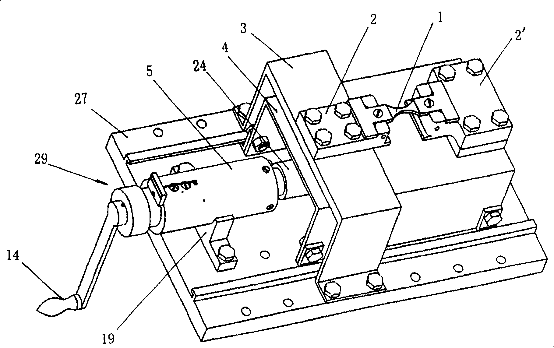
[0029] As shown in Figures 1 and 3.

[0030] A tension controllable manual hydraulic puller, which mainly consists of the following components:

[0031] A base 27, which can be fixedly connected to the machine tool workbench by bolts;

[0032] A fixed clamp body 3 connected to the base 27, the fixed clamp body 3 can be integrally connected with the base 27, and can also be connected by connecting bolts;

[0033] A movable pliers body 4 that can move linearly under the guidance of the base 27 and the fixed pliers body 3;

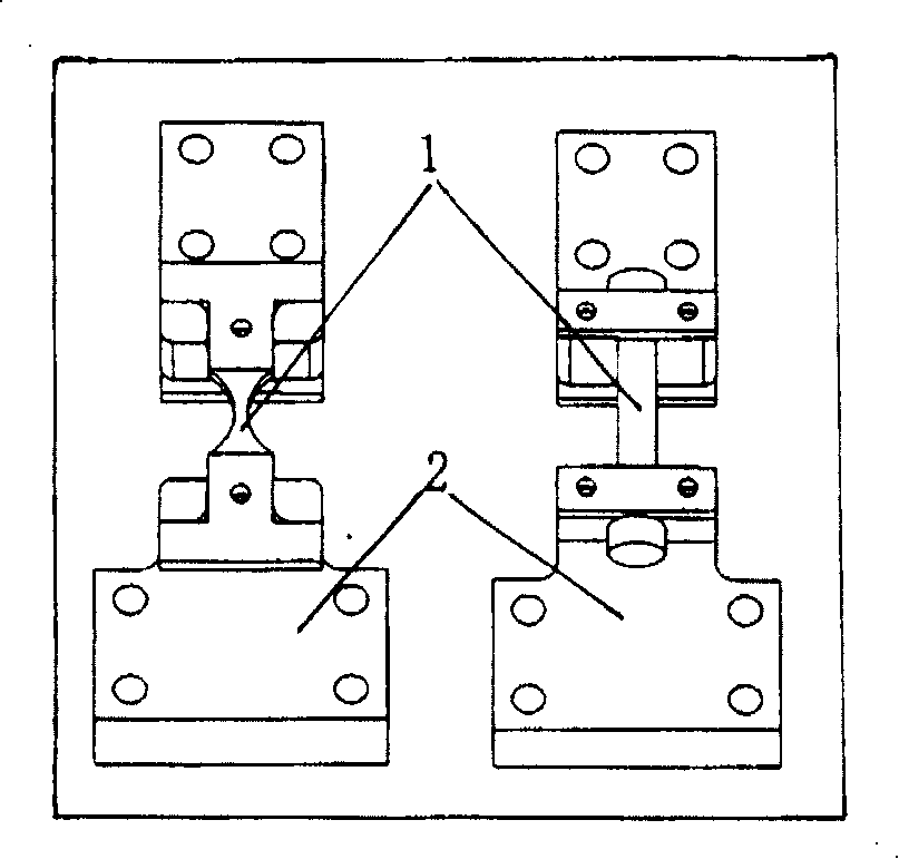
[0034] Two positioning blocks 2, 2' connected to the fixed pliers body 3 and the movable pliers body 4 respectively for clamping the workpiece 1, the shape of the positioning blocks 2, 2' is related to the shape of the workpiece, image 3 Shown are positioning blocks of two structures, one of which is a positioning block for a plate-shaped workpiece, and th...


PUM


Abstract

A stretch force controllable hand operated hydraulic pull tool use as the attachment of machine-tool for applying a stretch force to workpiece is disclosed. It features the combination of mechanical advancing with hydraulic loading.

Description

technical field [0001] The present invention relates to a fixture, especially a kind of machine tool fixture that is used to apply a certain tension force to a clamped workpiece in mechanical processing so as to achieve the purpose of changing the mechanical properties of the workpiece through stress recovery after processing, specifically a A kind of tensile force controllable manual hydraulic puller. Background technique [0002] In order to improve the fatigue performance of mechanical parts, it has been found that applying a certain tension to the parts during the processing of the parts has a unique effect. Tensile force, and then the workpiece is cut under the action of the tensile force, and the tensile load is removed from the workpiece after the processing is completed, so that the residual stress on the processed surface is redistributed, so as to obtain a satisfactory surface residual compressive stress, And to achieve the control of residual stress level. [00...

Claims


Application Information

Patent Timeline
Patent Type & Authority Patents(China)
IPC IPC(8): B23P25/00
Inventor 左敦稳许鸿昊朱笑笑张丹布光斌
Owner NANJING TOOLING
Why Eureka
Try Eureka