Method for manufacturing optical element

A manufacturing method and technology for optical components, applied in the directions of optical components, optics, manufacturing tools, etc., can solve the problems affecting the accuracy of the outer diameter, the inconsistency of the optical axis and the centering axis, etc., and achieve easy rough machining, cheap manufacturing, and shape reduction. the effect of the restriction

Inactive Publication Date: 2008-04-02
ALPS ALPINE CO LTD
View PDF3 Cites 0 Cited by
  • Summary
  • Abstract
  • Description
  • Claims
  • Application Information

AI Technical Summary

Problems solved by technology

However, by performing rough surface processing with a centering machine, the optical axis and the centering axis are likely to be inconsistent, which may adversely affect the accuracy of the outer diameter.

Method used


Image

  • Method for manufacturing optical element
  • Method for manufacturing optical element
  • Method for manufacturing optical element

Examples


Embodiment Construction

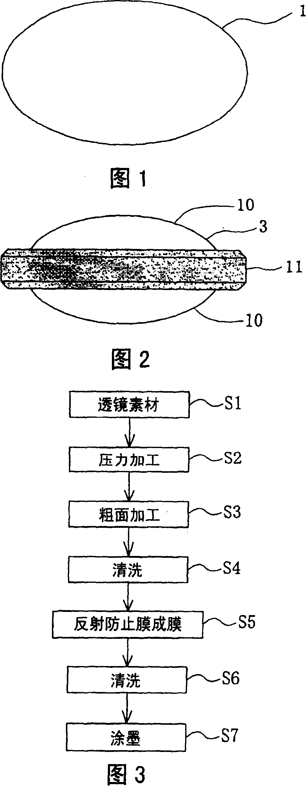
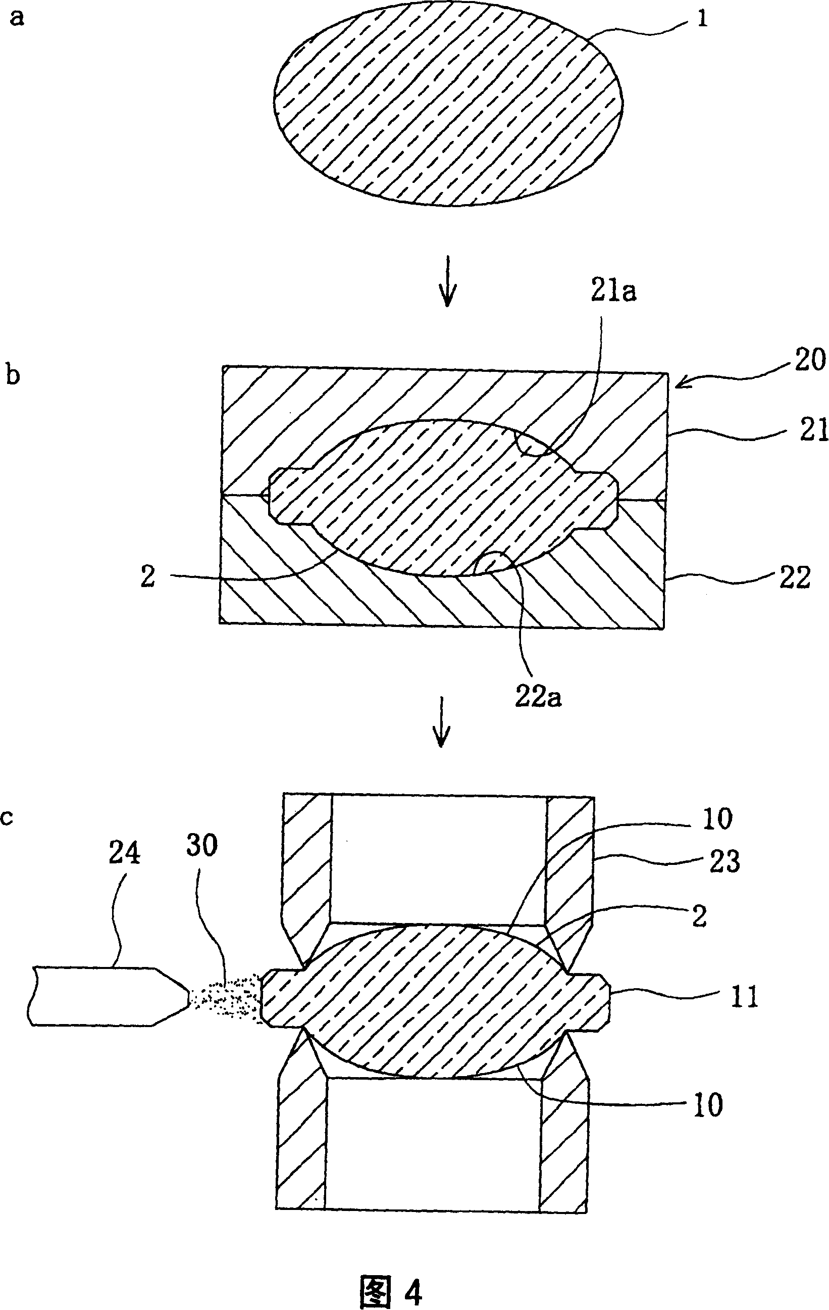
[0031] Hereinafter, embodiments of the present invention will be described in detail with reference to the drawings. FIG. 1 is a side view of a lens material 1 . FIG. 2 is a side view of the completed optical element 3 . The optical element 3 of this embodiment has optical function surfaces 10 and 10 on both surfaces, and a peripheral portion 11 is formed on the periphery thereof, and is formed by press working of glass. As shown in FIG. 1 , a lens material 1 called a protrusion which is preliminarily formed in an elliptical shape is prepared, heated and softened, and pressed with a die to form an optical element 3 shown in FIG. 2 .

[0032] The projection material 1 which is the lens material 1 can be formed into a predetermined shape by dropping an appropriate amount of glass material in a softened state from a glass melting furnace, changing the shape of the receiving part, and the like. In the present embodiment, the elliptical shape shown in FIG. 1 is shown, but other s...


PUM


Abstract

To provide a manufacturing method of an optical element capable of highly accurately and inexpensively performing rough surface processing on a peripheral edge part of an optical function surface, without performing the rough surface processing by a centering machine, when manufacturing the optical function surface by press working.This manufacturing method of the optical element comprises a process of applying the rough surface processing of a surface of the peripheral edge part 11 of the optical function surface 10 after forming an intermediate member 2 having the optical function surface 10 by press-working a lens raw material 1; and applies the rough surface processing to the surface of the peripheral edge part 11 by colliding a particle-like abrasive 30 with the surface outside of an end part of the fixed optical function surface 10 by fixing the intermediate member 2 from both surfaces over the substantially whole periphery in the end part of the optical function surface 10.

Description

technical field [0001] The present invention relates to a method of manufacturing an optical element having an optical function surface by pressing glass, and more particularly to a method of manufacturing an optical element having an anti-reflection portion for preventing light reflection formed on a peripheral portion of the optical function surface. Background technique [0002] As a method of manufacturing a lens made of glass, a method using grinding processing and a method using press processing are known. Among them, the lens manufacturing method using grinding processing is to bond and fix the glass material that is press-processed into an approximate shape that is one circle larger than the finished product on the jig, and to grind it with a suspended abrasive such as cerium oxide, thereby producing optical function. noodle. [0003] When producing an optical functional surface, centering processing is performed to eliminate the decentering of the optical axis from...

Claims


Application Information

Patent Timeline
Patent Type & Authority Patents(China)
IPC IPC(8): G02B3/00B24B13/00
Inventor 菊地公博
Owner ALPS ALPINE CO LTD
Why Eureka
Try Eureka