Shell and tube type heat exchanger having shell side multi path parallel flow inlet and outlet structure

A technology of shell-and-tube heat exchanger and side outlet, which is applied in the direction of heat exchanger types, indirect heat exchangers, lighting and heating equipment, etc., which can solve the problem of increased fluid baffle dead zone, good heat transfer performance, and heat exchanger Low operating energy consumption and other issues, to achieve the effect of reducing the flow dead zone, improving heat transfer performance, and saving equipment investment

Inactive Publication Date: 2008-02-13
SOUTH CHINA UNIV OF TECH
View PDF4 Cites 0 Cited by
  • Summary
  • Abstract
  • Description
  • Claims
  • Application Information

AI Technical Summary

Problems solved by technology

[0003] The purpose of the present invention is to solve and overcome the excessive number of rows of fluid cross-flow tubes at the inlet and outlet of the shell side, the excessive increase of flow resistance, and the increase of fluid baffle dead zone in the existing heat exchanger after the equipment is enlarged, which leads to the heat exchanger. Heater operation energy consumption increases, heat transfer performance declines, equipment material consumption increases, and the problems and shortcomings of investment increase provide a fluid cross-flow through a small number of tube rows, low flow resistance, small fluid baffle dead zone, and heat transfer. The shell-and-tube heat exchanger with low energy consumption, good heat transfer performance, low equipment material consumption, and investment saving shell side multi-channel parallel flow inlet and outlet structure

Method used


Image

  • Shell and tube type heat exchanger having shell side multi path parallel flow inlet and outlet structure
  • Shell and tube type heat exchanger having shell side multi path parallel flow inlet and outlet structure

Examples


Embodiment Construction

[0016] In order to better understand the present invention, the present invention will be further described below in conjunction with the accompanying drawings.

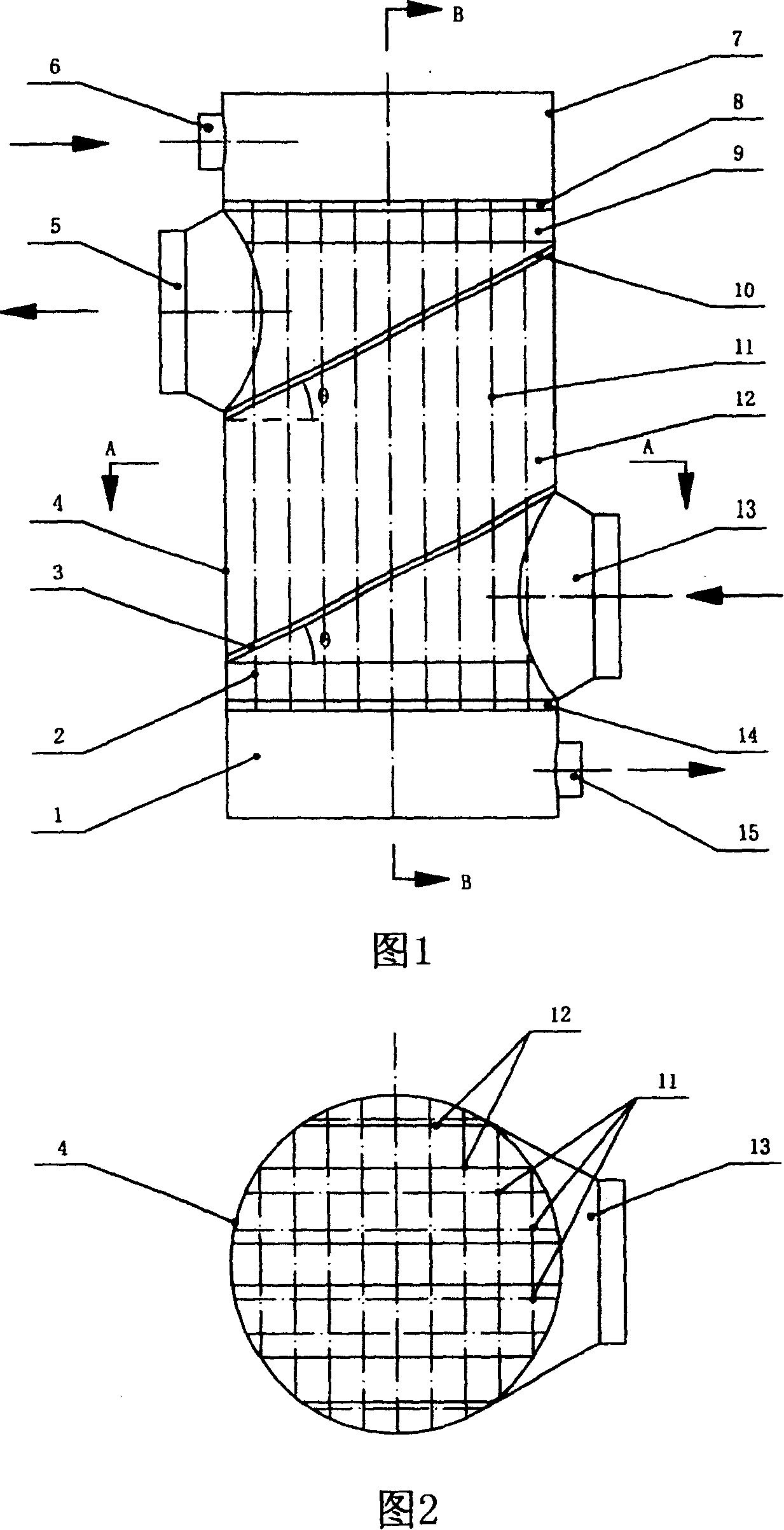
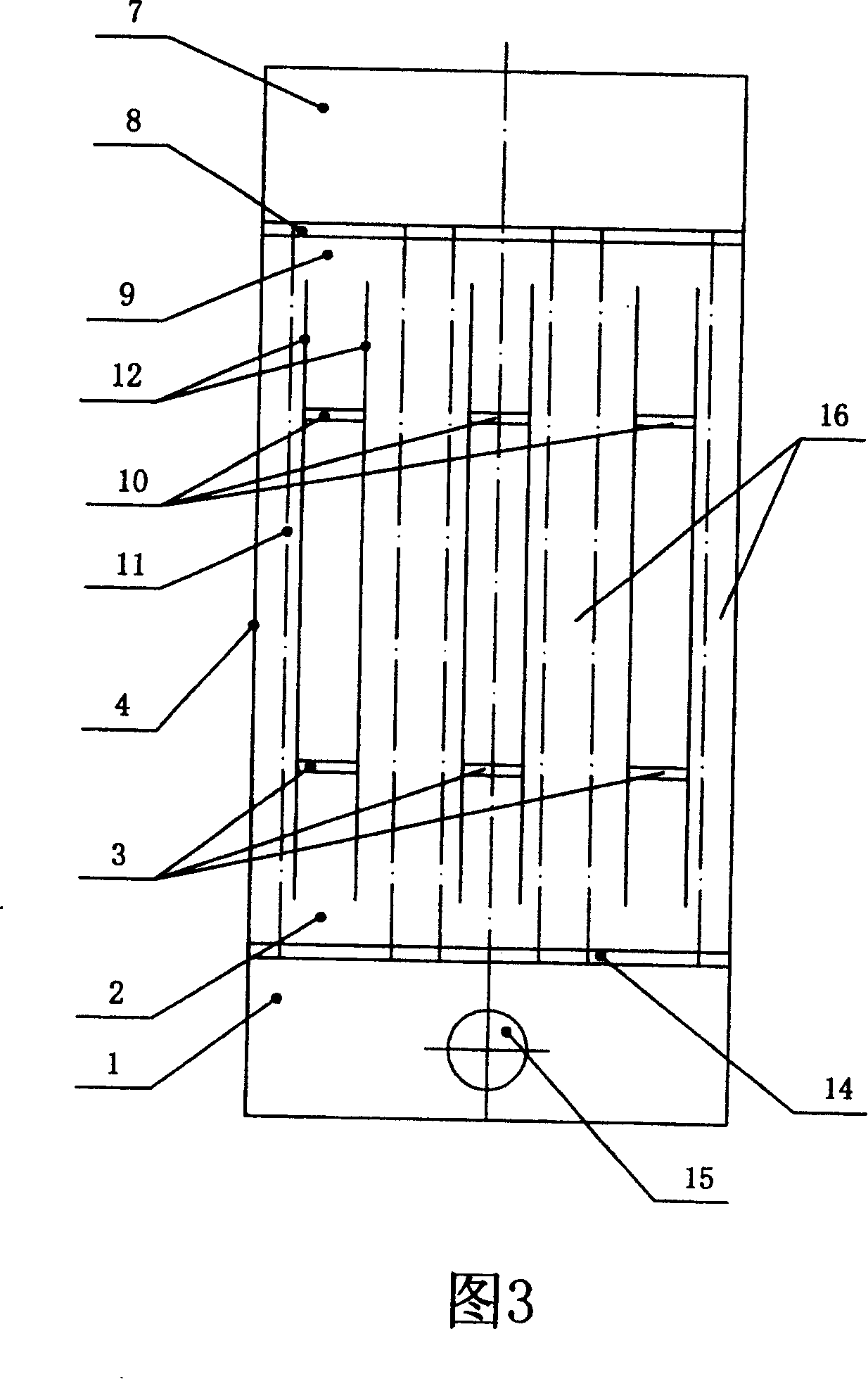
[0017] As shown in Figure 1, Figure 2 and Figure 3, the shell-and-tube heat exchanger with shell-side multi-channel parallel flow inlet and outlet structure of the present invention includes a lower head 1, a shell 4, a shell-side outlet 5, and a tube-side inlet 6 , upper head 7, upper tube sheet 8, heat transfer tube bundle 11, shell side inlet 13, lower tube sheet 14, tube side outlet 15, also includes shell side inlet notch 2, inlet baffle plate 3, shell side outlet notch 9, The outlet baffle 10 and the longitudinal baffle 12, the shell side inlet 13 are welded with the shell 4 and the lower tube plate 14 respectively, the lower tube plate 14 is welded with the lower head 1, and the lower head 1 is welded with the tube side outlet 15 The shell side outlet 5 is welded with the shell 4 and the upper tube plate 8 res...


PUM


Abstract

The present invention discloses a shell-and-tube heat exchanger with shell-side multi-channel parallel-flow inlet and outlet structure. It includes lower head, shell body, shell-side outlet, tube-side inlet, upper head, upper tube plate, heat-transferring tube bank, shell-side inlet, lower tube plate and tube-side outlet, and also includes shell-side inlet slot, inlet baffle plate, shell-side outlet slot, outlet baffle plate and longitudinal baffle plate.

Description

technical field [0001] The invention belongs to the field of shell-and-tube heat exchangers, in particular to a large-scale shell-and-tube heat exchanger with multi-channel parallel flow inlet and outlet structures. Background technique [0002] There are many shell-side structures of shell-and-tube heat exchangers, which are mainly divided into shell-side baffle heat exchangers and shell-side axial-flow heat exchangers. The shell-and-tube heat exchangers commonly used in industry with single-bow, double-bow or dish-ring baffles supporting tube bundles are shell-side baffle heat exchangers; industrially used baffle rods or hollow rings, etc. A shell heat exchanger is a shell side axial flow heat exchanger. The shell-and-tube heat exchangers of the above two shell-side structures all adopt a single-channel shell-side inlet and outlet structure. With the continuous enlargement of industrial equipment, the above-mentioned heat exchangers have the following defects: the heat ex...

Claims


Application Information

Patent Timeline
Patent Type & Authority Patents(China)
IPC IPC(8): F28D7/00F28D7/16
Inventor 邓先和张亚君
Owner SOUTH CHINA UNIV OF TECH
Why Eureka
Try Eureka