Motor-driven vane pump

A vane pump and vane technology, which is applied in pumps, mechanical equipment, machines/engines, etc., can solve the problems of high noise and leakage of power units, and achieve the effect of reliable sealing, low noise and compact structure

Inactive Publication Date: 2008-02-06
LANZHOU UNIVERSITY OF TECHNOLOGY
View PDF7 Cites 0 Cited by
  • Summary
  • Abstract
  • Description
  • Claims
  • Application Information

AI Technical Summary

Problems solved by technology

In addition, the electric motor connected to the vane pump contains cooling fans, so the noise of the whole power unit is also relatively large; at the same time, because the vane pump has an overhanging shaft, there is a leakage path

Method used


Image

  • Motor-driven vane pump

Examples


Embodiment Construction

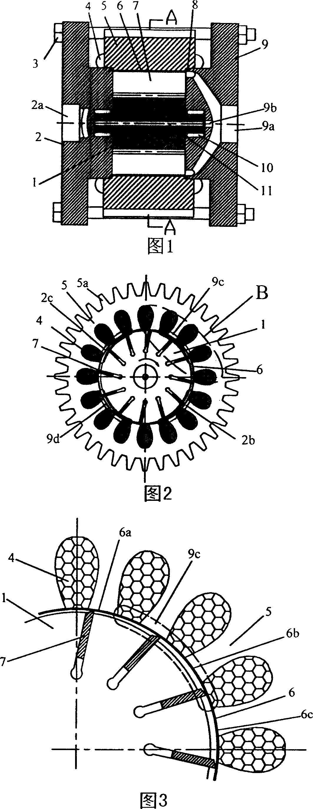
[0011] As shown in Figures 1 to 3, the present invention includes: a plurality of vanes 7 are evenly distributed in the motor rotor 1, the motor rotor 1 is supported in the front pump cover 9 and the rear pump cover 2 by the bearings 10 at both ends of the motor rotor 1, and the motor stator 5 The motor winding 4 is installed in the middle, and the motor stator 5 is provided with an anti-wear insulating coating 6 inside. A sealing ring 8 is installed between the motor stator 5 and the front pump cover 9 and the rear pump cover 2. The front pump cover 9 and the rear pump cover 2 Fastened together with the motor stator 5 by bolts 3.

[0012] The shape of the inner surface of the anti-wear insulating coating 6 is a waist circle composed of two sections of small arcs 6a, two sections of large arcs 6c and four sections of transition curves 6b. The outer circle of the motor stator 5 is evenly distributed with a plurality of cooling bands 5a.

[0013] The motor rotor 1 has a central ...


PUM


Abstract

The motor driven vane pump has motor winding driving the rotor of the vane pump directly so as to convert electric energy directly into hydraulic energy. The motor rotor with homogeneously distributed vanes is supported via bearings in two ends on the front pump cap and the back pump cap. The motor stator has inside winding and antiwear insulating coating. Between the motor stator and the front pump cap and between the motor stator and the back pump cap, there are sealing rings. The front pump cap, the back pump cap and the motor stator are fastened together with screws.

Description

technical field [0001] The invention relates to a hydraulic transmission device, in particular to a vane pump in a hydraulic pump. Background technique [0002] Vane pump is a structural form of hydraulic pump, which has the advantages of good flow uniformity and low noise, so it has been widely used. At present, the vane pump, as an independent hydraulic power component, needs to be connected with an independent electric motor or internal combustion engine to form a motor-hydraulic pump unit through its extended pump shaft. This connection requires devices such as couplings and pump frames. Due to the independent The motor volume of the hydraulic power unit is relatively large, and with accessories such as couplings, the volume and weight of the entire hydraulic power unit are very large. In addition, the motors connected to the vane pump all contain cooling fans, so the noise of the whole power unit is also relatively large; at the same time, because the vane pump has an ...

Claims


Application Information

Patent Timeline
Patent Type & Authority Patents(China)
IPC IPC(8): F04C2/344
Inventor 冀宏胡启辉王峥嵘张玮魏列江
Owner LANZHOU UNIVERSITY OF TECHNOLOGY
Why Eureka
Try Eureka