Laser lofting apparatus

A laser and laser beam technology, applied in measuring devices, instruments, surveying and navigation, etc., can solve the problems of cross-hair cursor limitation and inconvenient operation, and achieve the effect of simple and compact overall structure, convenient operation and small size

Inactive Publication Date: 2008-01-23
莱赛激光科技股份有限公司
View PDF7 Cites 0 Cited by
  • Summary
  • Abstract
  • Description
  • Claims
  • Application Information

AI Technical Summary

Problems solved by technology

The automatic leveling laser marking device disclosed in the utility model patent specification of Chinese patent authorization announcement number CN2502234Y can be placed on the front blocking surface through a horizontal line laser generator and two vertical line laser generators on both sides of the horizontal line laser generator. Form a horizontal line cursor and two straight line cursors vertically intersecting with the horizontal line cursor, thus forming two crosshair cursors, but the display of the crosshair cursor is limited by the direction, if you want to change the direction to display the crosshair cursor on the blocking surface, the The utility model is inconvenient to operate

Method used


Image

  • Laser lofting apparatus
  • Laser lofting apparatus
  • Laser lofting apparatus

Examples


Embodiment Construction

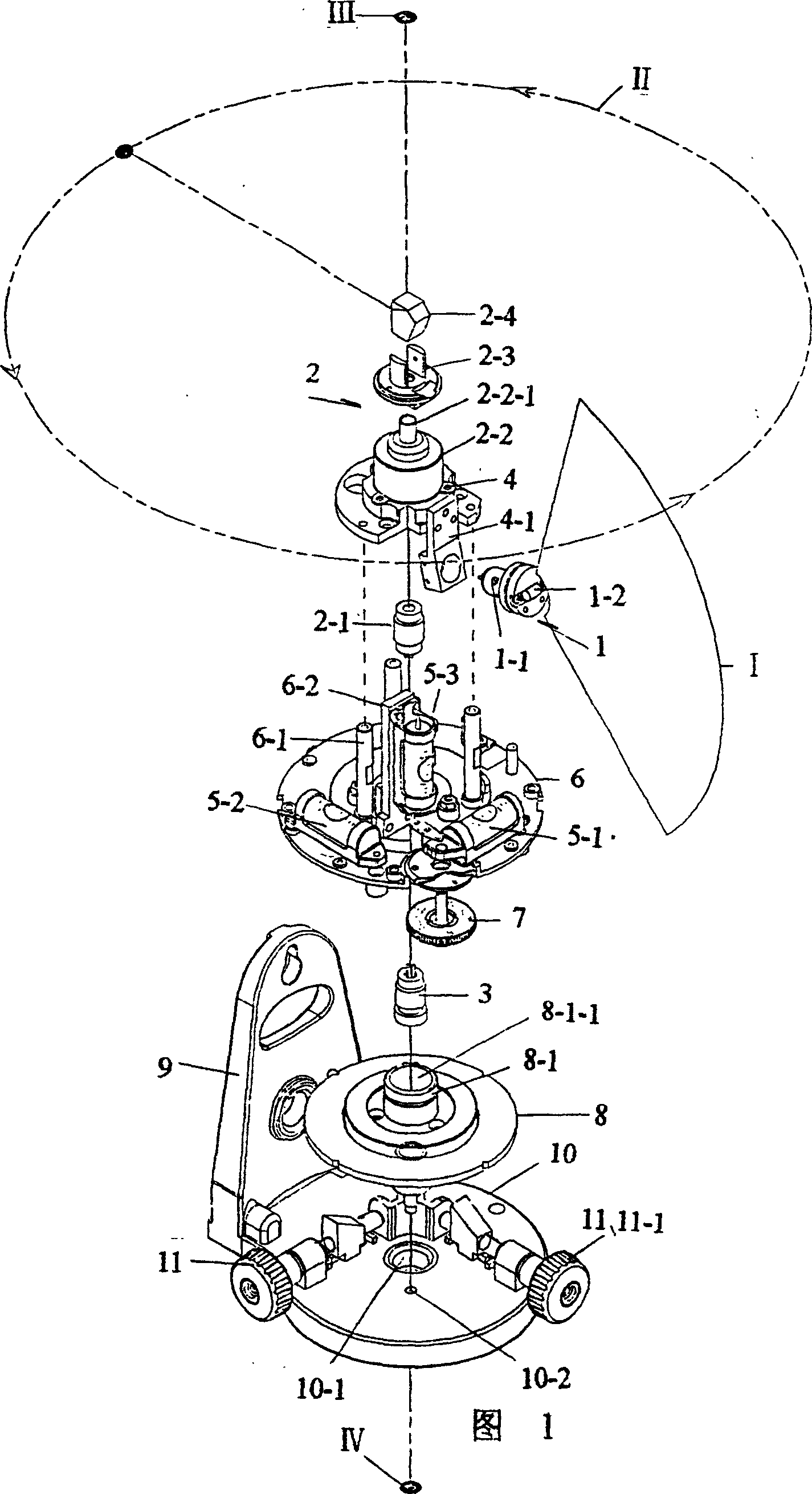
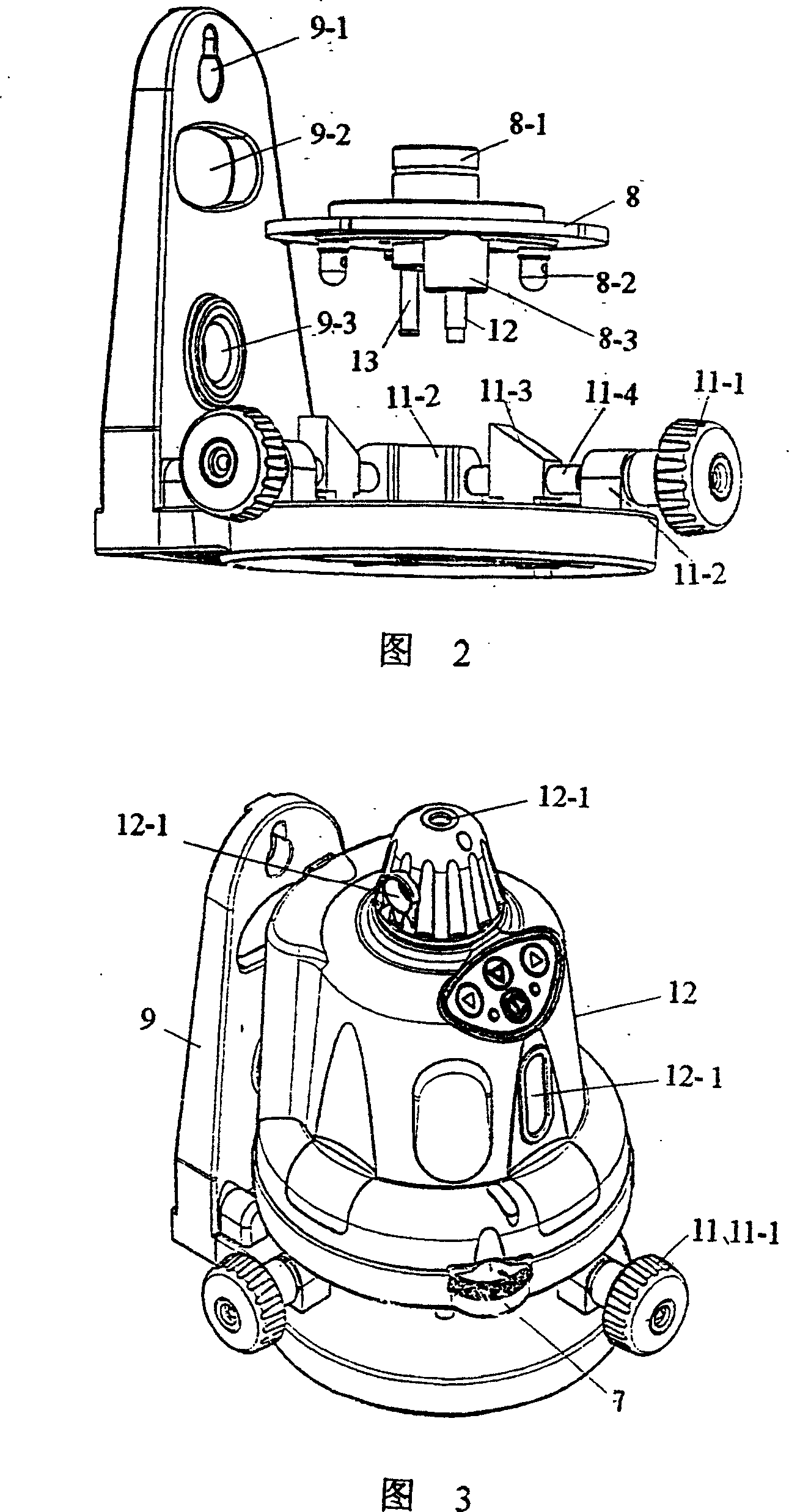
[0021] As shown in the drawings, the present invention has a base body, a line laser component 1 and a point laser component 2 . The base body includes a base 10, a tray 8, a base frame 6, and levels 5-2, 5-1, and 5-3 respectively in the X, Y, and Z coordinate axes. The base 10 is provided with a central hole 10-1; Y , The X-coordinate axial level 5-1, 5-2 is fixed on the base frame 6 at 90°, and the Z-coordinate axial level 5-3 is fixed on the support 6-2 of the base frame 6. The base frame 6 is connected with the tray 8 for relative rotation. Between the base 10 and the tray 8, there are two wedge adjustment mechanisms 11, ball studs 12, and stopper components fixed on the base 10 and corresponding to the levelers 5-2 and 5-1 in the X and Y coordinate axes. and spring (not shown). The ball stud 12 is between the two wedge adjustment mechanisms 11, the lower end of the ball stud 12 is inserted into the strut positioning hole 10-3 of the base 10, the ball end is in the ball ...


PUM


Abstract

The present ivnention relates to a laser laying-out equipment, it has base body, linear laser component formed from first laser component and cylindrical lens and point laser component formed from second laser component and rotating prism component; the laser beam transmitted by first laser component can display vertical line cursor on the front obstacle; the laser beam transmitted by second laser component can display plane-scanning line cursor on the peripheric obstacle; the sector laser surface sent out by first laser component and the plane-scanning laser surface sent out by second laser component are crossed, and a cross-line cursor can be displayed on the obstacle, and said cross-line cursor is moved with the rotation of line laser component which is rotated round the central line of the point laser component. Said invention is simple in operation, and can provide convenience for laying-out work.

Description

technical field [0001] The invention relates to a device for displaying marking lines. Background technique [0002] When staking out in construction, decoration, and decoration projects, it is necessary to display horizontal lines, vertical lines, and cross lines on the working surface. The reflective laser marking instrument disclosed in the utility model patent specification of China Patent Authorization Announcement No. CN2366925Y is provided with three levels on the surface of its shell, which are respectively in the directions of X, Y, and Z coordinate axes, and a laser is fixed inside the shell. Source, corresponding to the beam direction of the laser source, there is a mirror with an angle of 40-50 degrees to the beam, and the mirror can rotate 360 ​​degrees around the beam of the laser source to form a sweeping line. When the utility model is in use, the instrument shell is fixedly installed on the adjustment seat horizontally to display the horizontal line, or ins...

Claims


Application Information

Patent Timeline
Patent Type & Authority Patents(China)
IPC IPC(8): G01C15/00G01D21/02
Inventor 陆建红
Owner 莱赛激光科技股份有限公司
Why Eureka
Try Eureka