Volume expander and fluid machine
A volumetric, expander technology, applied in mechanical equipment, machines/engines, rotary piston machines, etc., to achieve a simple structure, improve power recovery efficiency, and prevent the action from becoming unstable.
- Summary
- Abstract
- Description
- Claims
- Application Information
AI Technical Summary
Problems solved by technology
Method used
Image

Examples
Embodiment approach 1
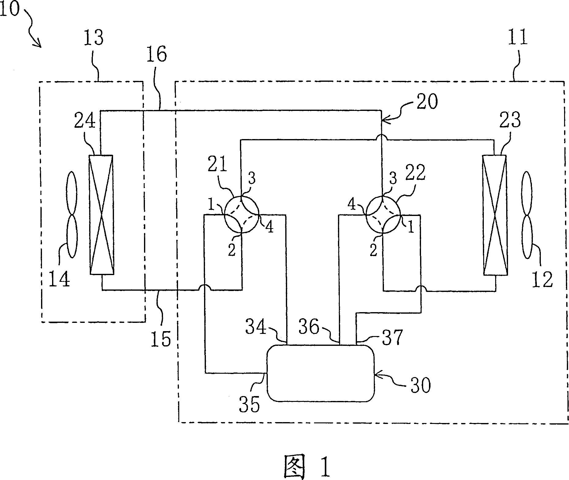
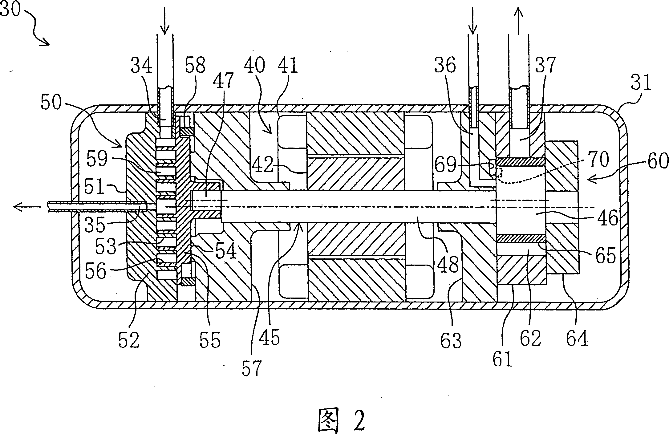
[0062] Embodiments of the present invention will be described in detail below with reference to the drawings. In Embodiment 1, an air conditioner 10 is configured using the fluid machine of the present invention.
[0063] (The overall structure of the air conditioner)
[0064] As shown in FIG. 1 , the air conditioner 10 described above is a so-called separate type air conditioner and includes an outdoor unit 11 and an indoor unit 13 . The outdoor unit 11 accommodates an outdoor fan 12 , an outdoor heat exchanger 23 , a first four-way switching valve 21 , a second four-way switching valve 22 , and a compression / expansion unit 30 . An indoor fan 14 and an indoor heat exchanger 24 are housed in the indoor unit 13 . Furthermore, the outdoor unit 11 is installed outdoors, and the indoor unit 13 is installed indoors. In addition, the outdoor unit 11 and the indoor unit 13 are connected by a pair of communication pipes 15 and 16 . Note that the details of the compression / expansio...
Embodiment approach 2
[0122] Embodiment 2 of the present invention, as shown in FIG. 15 , is an example in which a solenoid valve 77 is provided instead of a check valve 73 in the communication pipe 72 of the expansion part 60 in the fluid machine of the first embodiment. In Embodiment 2, one end of the communication pipe 72 is connected to the outflow port 37 side, and the other end is directly connected to the cylinder 61 to communicate with the expansion chamber 62 .
[0123] The solenoid valve 77 is configured to open when the expansion chamber 62 is over-expanded, similarly to the check valve 73 in the first embodiment. Therefore, in the air conditioner 10 according to Embodiment 2, in addition to the high-pressure pressure sensor 78a generally provided on the refrigerant circuit 20, an over-expansion pressure sensor 78b for detecting the pressure of the expansion chamber is provided. And, when the control unit 79 of the air conditioner 10 determines that over-expansion has occurred based on t...
Embodiment approach 3
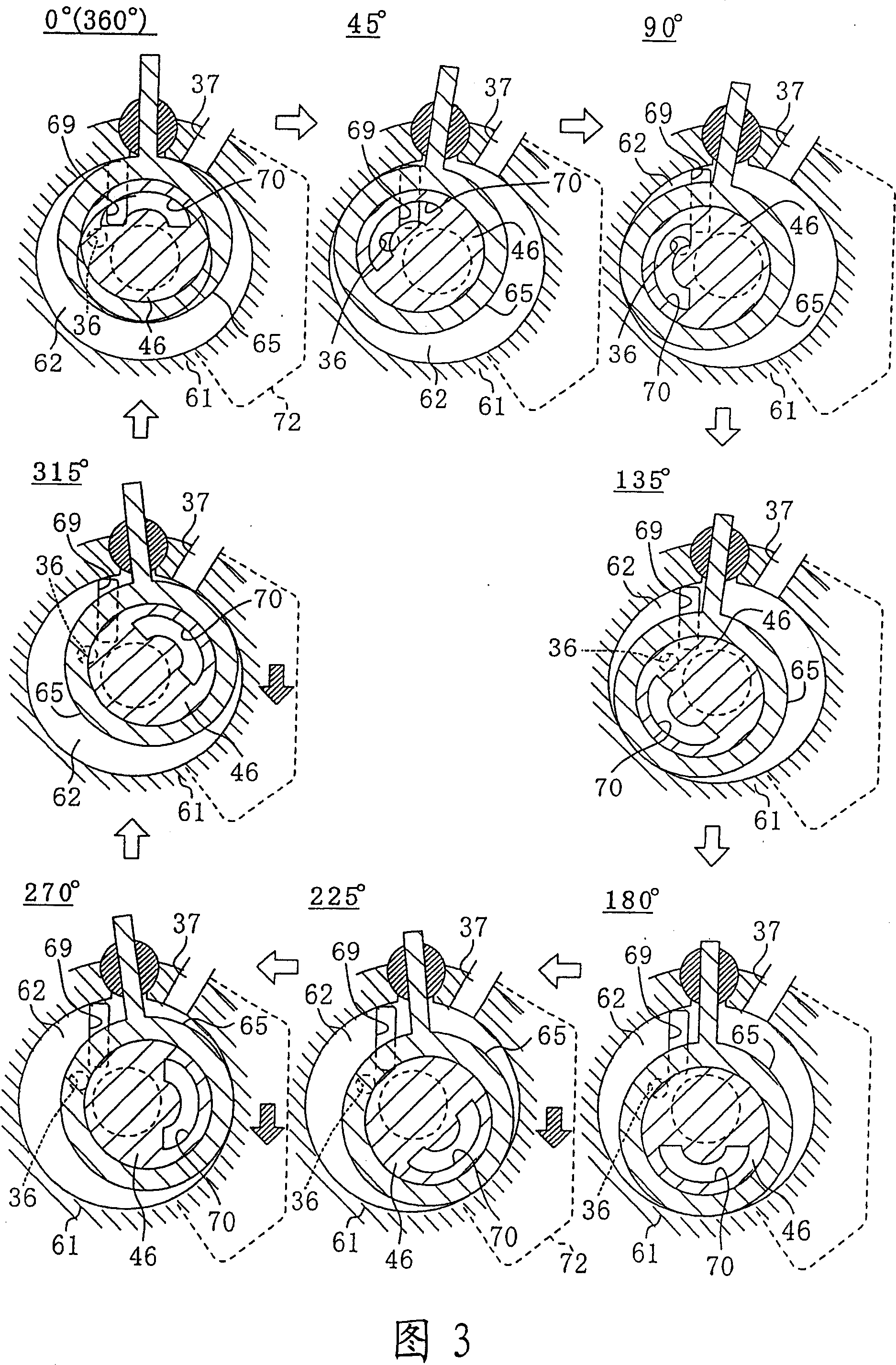
[0127] Embodiment 3 of the present invention is an example in which the structure of the communication passage in the middle of the expansion process communicating the outflow port 37 and the expansion chamber 62 is changed compared with the first and second embodiments.
[0128] In Embodiments 1 and 2, an example in which a communication pipe 72 is provided as a communication passage has been described, but in Embodiment 3, as shown in FIGS. 16(a) and 16(b), a communication passage 80 is formed in Inside the cylinder 61 which is a component of the expansion mechanism unit 60 . As the communication channel 80 , a first recessed portion 81 is formed on the surface of the cylinder 61 on the side of the occipital head 64 , and a second recessed portion 82 is formed on the surface of the cylinder 61 on the side of the front head 63 . In addition, the cylinder 61 is formed with: a communicating hole 83 communicating with the first recessed portion 81 and the second recessed portion...
PUM
 Abstract
Description
Claims
Application Information
 - R&D
- Intellectual Property
- Life Sciences
- Materials
- Tech Scout
- Unparalleled Data Quality
- Higher Quality Content
- 60% Fewer Hallucinations
Browse by: Latest US Patents, China's latest patents, Technical Efficacy Thesaurus, Application Domain, Technology Topic, Popular Technical Reports.
© 2025 PatSnap. All rights reserved.Legal|Privacy policy|Modern Slavery Act Transparency Statement|Sitemap|About US| Contact US: help@patsnap.com