
Robot for cerebral surgery operation

A brain surgery and robotic technology, applied in the fields of surgery, manipulators, medical science, etc., can solve the problems of few surgical indications, single function, limited clinical application and application, and achieve the effect of wide surgical field and simple structure.

Inactive Publication Date: 2007-10-31
梁四成
View PDF4 Cites 0 Cited by
  • Summary
  • Abstract
  • Description
  • Claims
  • Application Information

AI Technical Summary

Problems solved by technology

However, since there is only one straight channel with relatively simple functions, only some simple operations can be performed, and there are few surgical indications, and complex intracranial operations cannot be performed, so the clinical application is limited.

Method used


Image

  • Robot for cerebral surgery operation
  • Robot for cerebral surgery operation
  • Robot for cerebral surgery operation

Examples


Embodiment Construction

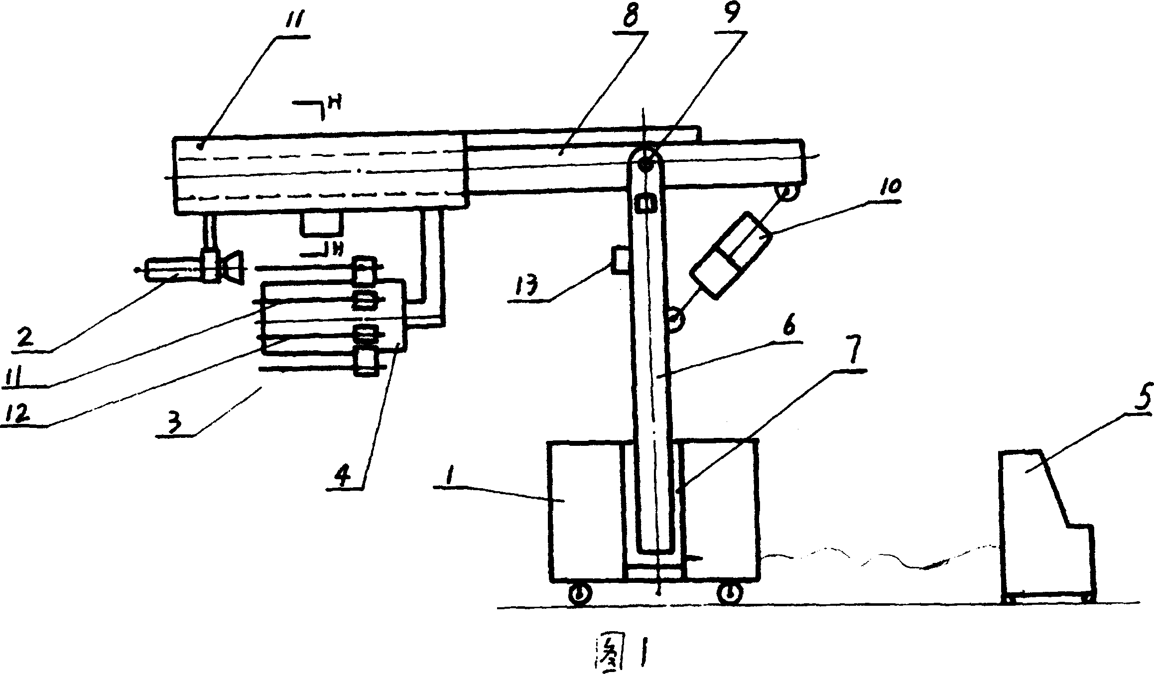
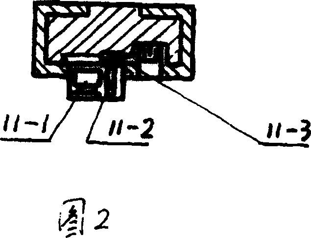
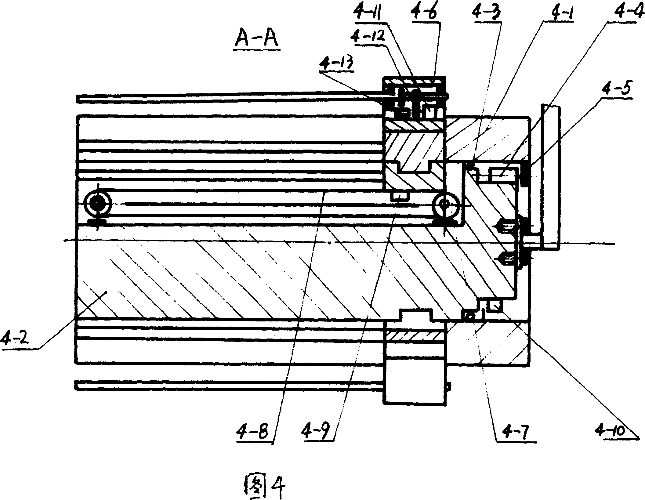
[0020] In conjunction with Fig. 1, Fig. 2, Fig. 3, Fig. 4... Fig. 10 elaborates the details and working conditions of the present invention, the present invention mainly consists of hydraulic support 1, guide pipe 2, finger 3, roller 4, sliding box 11, console 5 and other six parts, the vertical beam 6 of the hydraulic support 1 is essentially the piston rod of the hydraulic cylinder 7. The height of the hydraulic support is adjusted by controlling the hydraulic cylinder 7. The crossbeam 8 and the vertical beam 6 are connected by a hinge 9. A rail is designed on the crossbeam 8. A sliding box 11 is installed on the rail. The sliding box 11 is connected with a roller 4 and a guide. The tube 2 and the slide box 11 are equipped with a motor 11-1, the gear 11-2 on the output shaft of the motor 11-1 meshes with the rack 11-3 on the track, and the motor 11-1 can drive the slide box 11 along the beam 8 The track moves back and forth; the guide tube 2 is the channel for surgical instr...


PUM


Abstract

A robot for the cerebrosurgical operation is composed of hydraulic supporting frame with hydraulic cylinder installed between vertical and transverse beams and the guide track on said transverse beam, the slide box on said guide track, robot fingers, drum, the light source and imaging system on said pilot tube and robot fingers, and console. Its advantages are simple structure and wide visual field.

Description

1. Technical field [0001] The present invention relates to a medical device for brain surgery. 2. Background technology [0002] With the rapid development of science and technology, advanced medical equipment has been more and more widely used in brain surgery. However, the existing technology can only realize the location of brain lesions and some simple operations. Chinese Patent No. CN1243690A discloses a "Robot Brain Surgery Equipment System and Its Implementation Method". This technology can accurately measure the location of brain lesions and help Determine surgical treatment options and assist with biopsy, resection, and radiation therapy. However, since there is only one straight channel with relatively simple functions, only some simple operations can be performed, and there are few surgical indications, and complex intracranial operations cannot be performed, so the clinical application is limited. 3. Contents of the invention [0003] The purpose of the prese...

Claims


Application Information

Patent Timeline
Patent Type & Authority Patents(China)
IPC IPC(8): B25J11/00A61B17/00
Inventor 梁四成
Owner 梁四成
Learn More