A ceramic casting device
A technology of ceramics and mounting plates, applied in ceramic molding machines, manufacturing tools, etc., can solve the problems of inaccurate drawing effect and inability to meet drawing requirements
- Summary
- Abstract
- Description
- Claims
- Application Information
AI Technical Summary
Problems solved by technology
Method used
Image
Examples
specific Embodiment approach 1
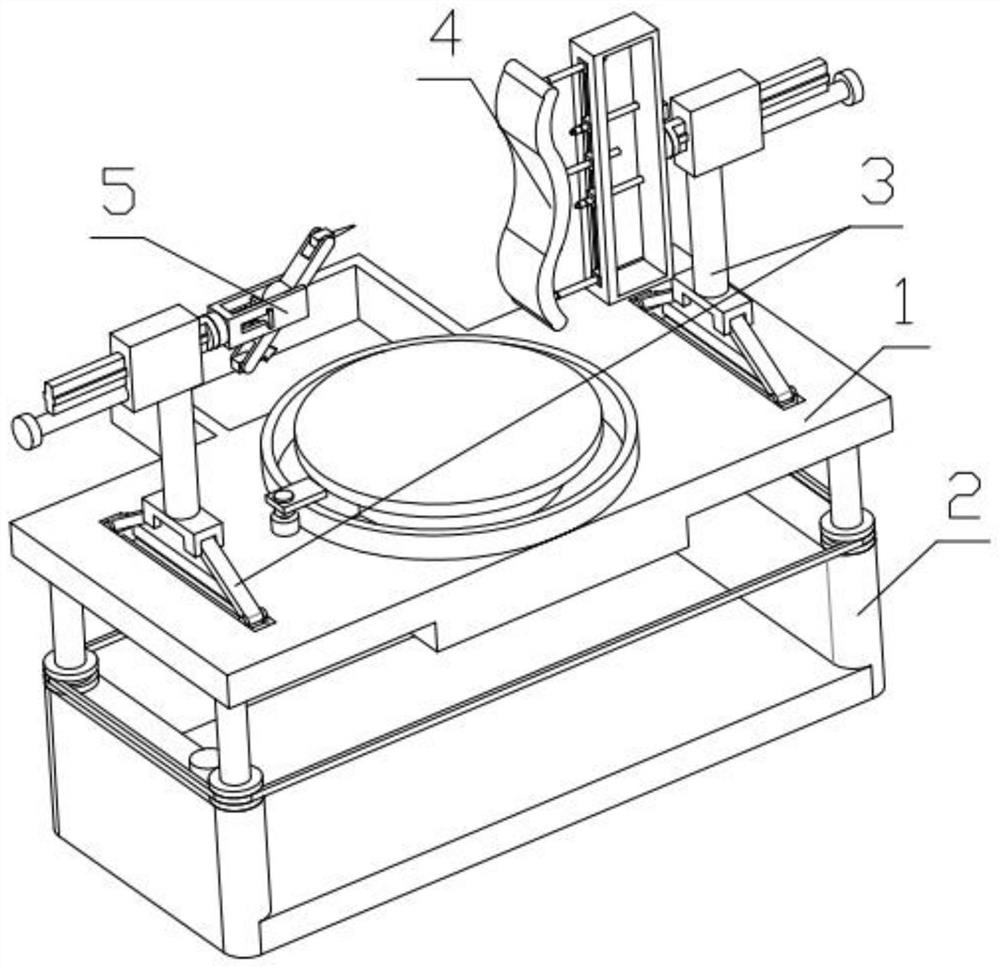
[0035] Combine below Figure 1-14 In this embodiment, a ceramic drawing device includes a rotation and cleaning mechanism 1, a height adjustment mechanism 2, a position adjustment mechanism 3, a shaping mechanism 4 and a scoring mechanism 5, and the height adjustment mechanism 2 is fixedly mounted on a rotating And on the cleaning mechanism 1, there are two position adjustment mechanisms 3, which are respectively fixedly installed on the two ends of the rotation and cleaning mechanism 1. One position adjustment mechanism 3 is fixedly equipped with a shaping mechanism 4, and the other position adjustment mechanism 3 A scoring mechanism 5 is fixedly installed on the top.
specific Embodiment approach 2
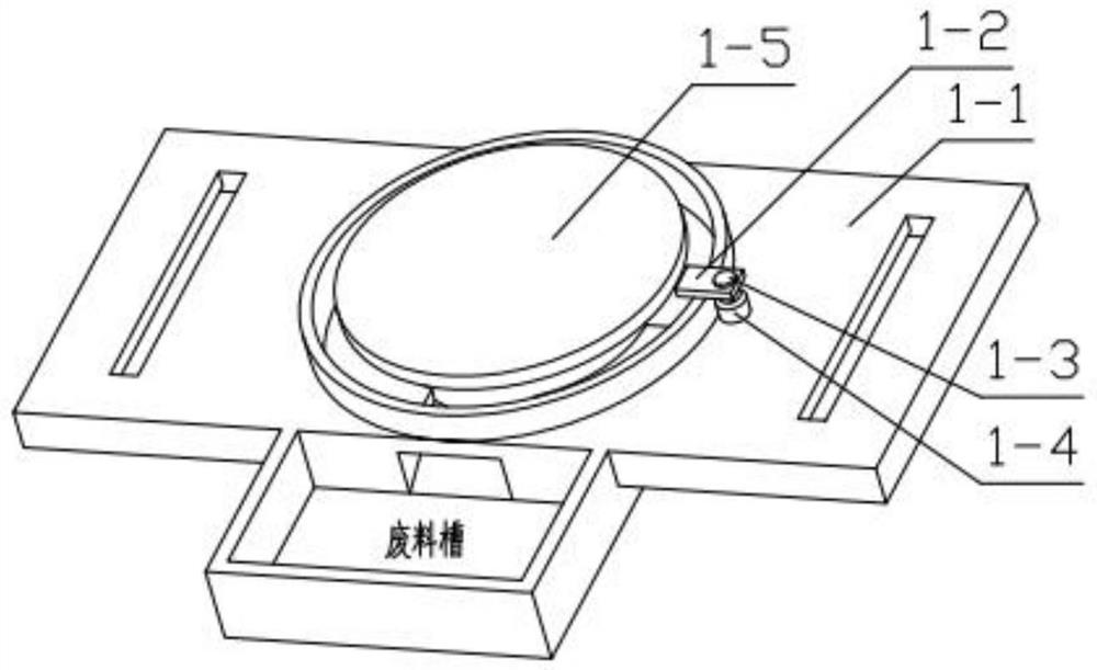
[0036] Combine below Figure 1-14 Describe this embodiment, this embodiment will further explain the first embodiment, the rotation and cleaning mechanism 1 includes the main mounting plate 1-1, scraper 1-2, scraper motor 1-3, scraper gear 1 -4, porcelain clay rotating disk 1-5, rotating motor 1-6, rotating motor 1-6 is fixedly installed in the groove provided on the main mounting plate 1-1, and porcelain clay rotating disk 1-5 is fixedly installed on The output end of the rotating motor 1-6, the scraper 1-2 is slidably installed in the groove provided on the main mounting plate 1-1, the scraper motor 1-3 is fixedly installed on the scraper 1-2, and the scraper The gear 1-4 is fixedly installed on the output end of the scraper motor 1-3, and the scraper gear 1-4 is meshed with the main mounting plate 1-1.
specific Embodiment approach 3
[0037] Combine below Figure 1-14 Describe this embodiment, this embodiment will further explain the second embodiment, the height adjustment mechanism 2 includes a threaded column 2-1, a limit sprocket ring 2-2, a chain 2-3, and a lifting gear 2-4 , U-shaped bottom plate 2-5, lifting motor 2-6, limit sprocket ring 2-2 is installed in the groove provided by U-shaped bottom plate 2-5, and lifting motor 2-6 is fixedly installed on U-shaped bottom plate In the groove provided by 2-5, the lifting gear 2-4 is fixedly installed on the output end of the lifting motor 2-6, and the lifting gear 2-4 is meshed with the limit sprocket ring 2-2, and the limit sprocket The ring 2-2 is threadedly connected with the threaded column 2-1, the limit sprocket ring 2-2 is engaged with the chain 2-3, and the threaded column 2-1 is fixedly installed on the main mounting plate 1-1.
PUM
 Abstract
Description
Claims
Application Information
 - Generate Ideas
- Intellectual Property
- Life Sciences
- Materials
- Tech Scout
- Unparalleled Data Quality
- Higher Quality Content
- 60% Fewer Hallucinations
Browse by: Latest US Patents, China's latest patents, Technical Efficacy Thesaurus, Application Domain, Technology Topic, Popular Technical Reports.
© 2025 PatSnap. All rights reserved.Legal|Privacy policy|Modern Slavery Act Transparency Statement|Sitemap|About US| Contact US: help@patsnap.com


