
Method and system for reducing splash in gas shielded welding of short-circuiting transfer

A gas shielded welding and short-circuit transition technology, applied in welding equipment, arc welding equipment, manufacturing tools, etc., can solve the problems of difficult current waveform, rapid drop of liquid bridge current, and impossibility of rapid drop of liquid bridge current. To achieve the effect of reducing welding spatter

Inactive Publication Date: 2007-10-24
TSINGHUA UNIV
View PDF6 Cites 2 Cited by
  • Summary
  • Abstract
  • Description
  • Claims
  • Application Information

AI Technical Summary

Problems solved by technology

However, due to the lag of the movement of the welding wire in the wire feeding tube, it is impossible to synchronize the liquid bridge contraction process, the current control process and the welding wire movement process, so it can only be an ideal but impossible solution.
The third type of method is the method of waveform control. Due to the randomness and dispersion of the droplet transfer process, it is difficult to synchronize the preset current waveform with the droplet transfer process; and improper waveform control will affect the self-adjustment performance and arc performance. Weld penetration and shape
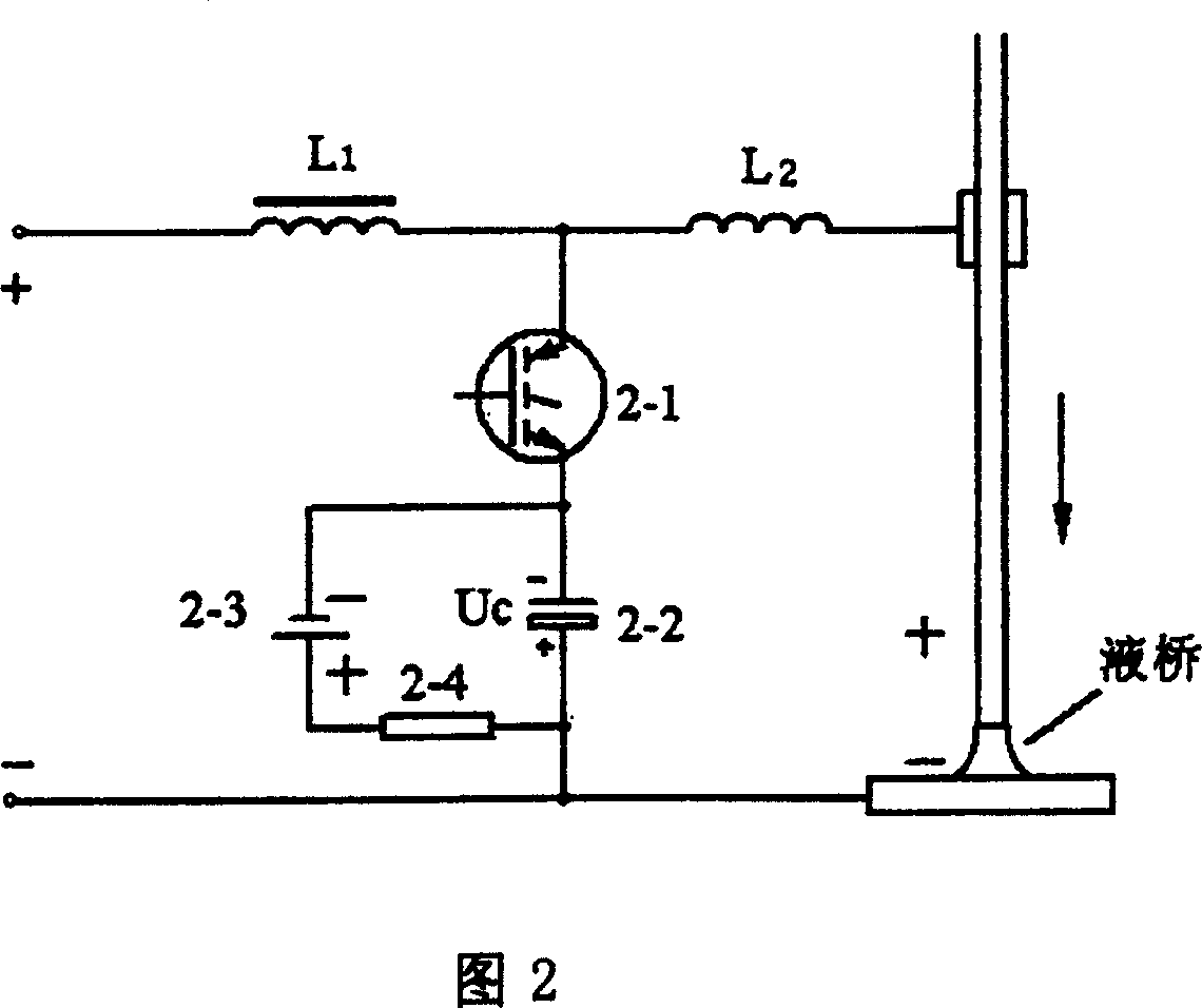
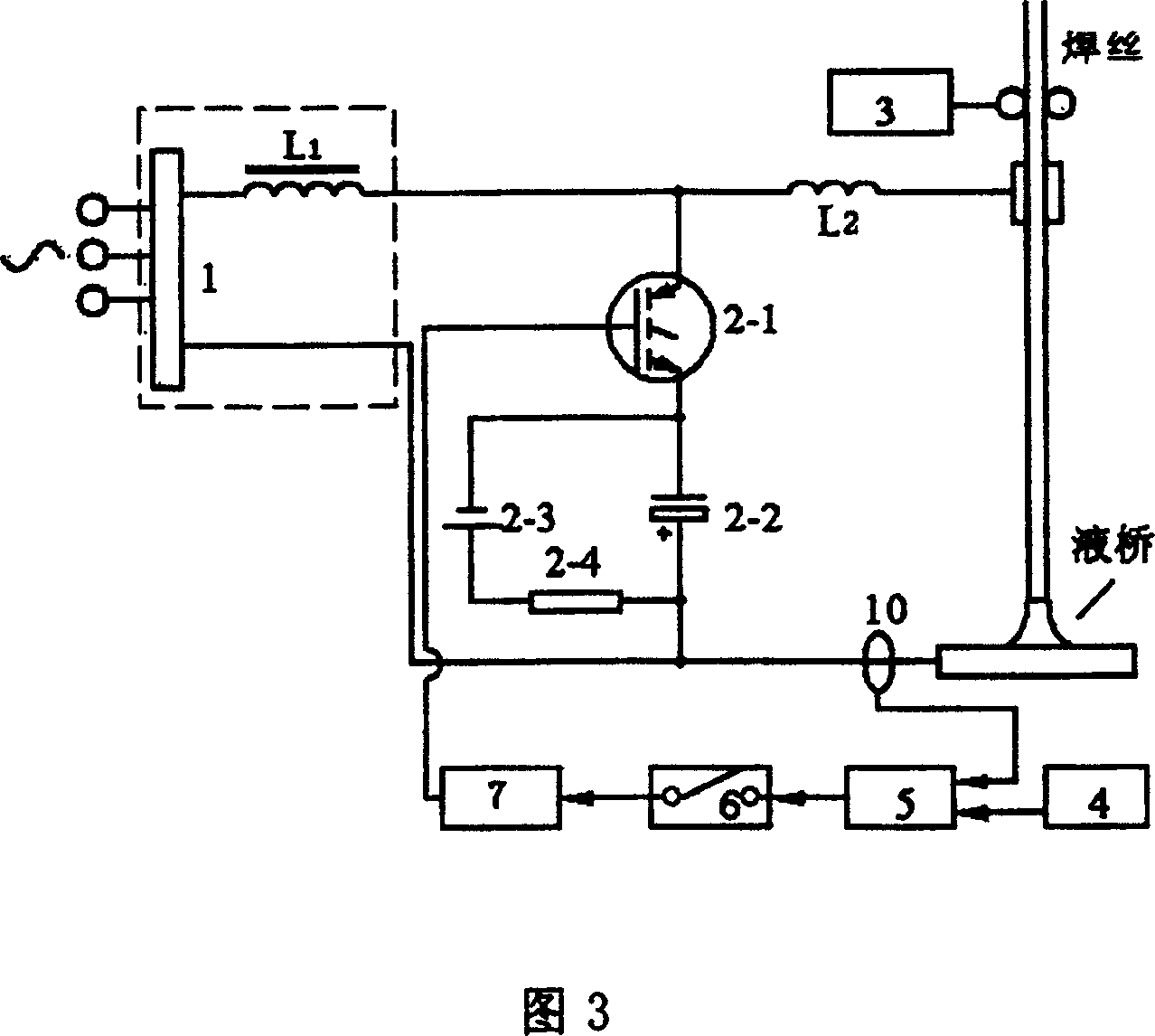
Some methods try to control the late stage current of the liquid bridge by connecting devices in series in the welding circuit, but because the liquid bridge current needs a fast drop speed, due to the existence of the above-mentioned series DC inductance of the welding machine, the rapidly changing liquid bridge current will be at both ends of the control device. There will be a high overvoltage, and conversely, the liquid bridge current cannot drop quickly
Also, having a control device in series in the welding loop creates significant power dissipation

Method used


Image

  • Method and system for reducing splash in gas shielded welding of short-circuiting transfer
  • Method and system for reducing splash in gas shielded welding of short-circuiting transfer
  • Method and system for reducing splash in gas shielded welding of short-circuiting transfer

Examples


Embodiment

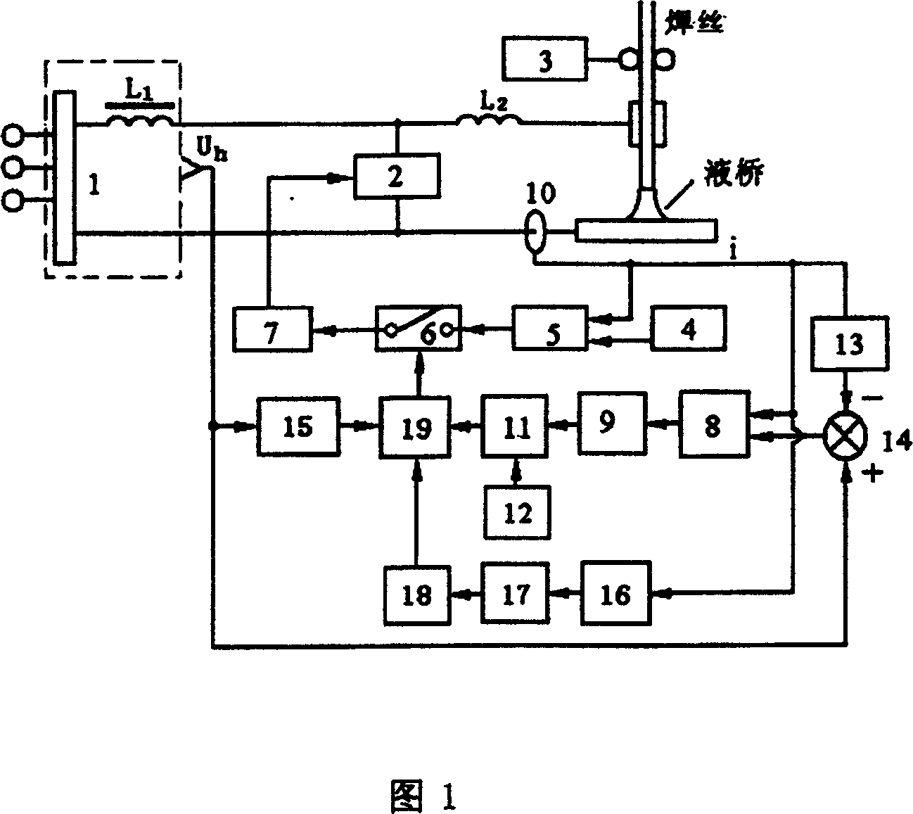
[0084] Figure 8 is the basic circuit diagram of the detection and judgment system for the shrinkage state of the short-circuit liquid bridge. Its function is to detect the state of the shrinkage process of the welding short-circuit liquid bridge, and use the resistance change rate of the welding circuit or the impedance change rate of the welding circuit to characterize the shrinkage degree of the short-circuit liquid bridge or liquid bridge diameter. And by comparing with the set value, when it reaches the set value, a trigger pulse is generated to open the short-circuit liquid bridge current closed-loop bypass control system.

[0085] The working principle of the circuit is as follows:

[0086] The voltage u is taken from the output voltage of the welding power supply in Figure 9, and the liquid bridge current i is taken from the current transformer of the welding circuit. Because the output voltage u of the power supply of the welding machine is not in common with the cont...


PUM


Abstract

A method for reducing splash in gas shielded welding of short-circuiting transfer is disclosed. The invention judges a short-circuiting liquid bridge diameter by detecting a resistance change rate of a welding circuit or an impedance change rate of the welding circuit during a welding process, when the short-circuiting liquid bridge diameter is reduced to a predetermined value, a liquid bridge current is rapidly falled by performing flow division control on the short-circuiting liquid bridge current, and the liquid bridge is held in a break state, thereby the short-circuiting liquid bridge is transferred flexibly under a condition of small current, welding splash is reduced. In addition, also disclosed is a system for realizing the method.

Description

technical field [0001] The invention relates to a welding method and equipment, in particular to a method for reducing spatter in short-circuit transitional gas shielded welding and a system for realizing the method. Background technique [0002] Short-circuit transition gas-shielded welding includes gas-shielded welding methods such as carbon dioxide gas-shielded welding, mixed gas shielded welding, and molten electrode argon arc welding. It has the advantages of high productivity, low cost, small welding deformation, wide application range, convenient all-position welding and easy realization of welding automation, etc., and has a wide range of applications in production. The main disadvantage of short-circuit transition gas shielded welding is the large welding spatter. Welding spatter deteriorates production conditions and environment, reduces the utilization rate of welding wire, destroys the stability of arc, and reduces the quality of weld seam. [0003] The traditi...

Claims


Application Information

Patent Timeline
Patent Type & Authority Patents(China)
IPC IPC(8): B23K9/10B23K9/173B23K9/073
Inventor 区智明
Owner TSINGHUA UNIV
Learn More