
Apparatus and method for bioelectric stimulation, healing acceleration and pain relief

Inactive Publication Date: 2012-05-08
MEDRELIEF
View PDF45 Cites 6 Cited by
  • Summary
  • Abstract
  • Description
  • Claims
  • Application Information

AI Technical Summary

Benefits of technology

[0041]The apparatus is lightweight, compact, self-contained, cost-effective to manufacture and maintain, and convenient to carry or wear for extended periods. It is safe for unsupervised home use without the need for special training, and able to generate the above-described output signal and deliver it efficiently through conductive pads making direct contact with the load. Since only low voltages and currents are used, the apparatus does not pose a shock hazard even in case of malfunction. Power is furnished by compact and inexpensive batteries, needing replacement only once in several weeks of use.
[0058]Another feature of the present invention is the provision of interval T7, during which intermediate voltage or current level L3 is presented to the load rather than low level L2. This feature minimizes the amount of low-frequency energy which is presented to the load (such as tissue being treated with the apparatus) during this resting interval between pulse bursts.
[0060]Yet another feature of the present invention is the use of dual timing blocks to generate waveforms that can be combined to produce an output waveform having selected desired characteristics. In a preferred embodiment of the invention, one of two timing blocks is controlled by the other: that is, the output of the second block is “on” or “off” depending on whether the output of the first block is “low” or “high,” respectively. This results in a circuit that generates an output signal whose characteristics—frequency, duty cycle, amplitude—can be determined over a wide range by the particular selection of components. Two such circuits with output signals having appropriately-selected characteristics can be combined to produce the desired output waveform, with timing intervals T1 through T7, with a surprisingly simple overall circuit configuration.

Problems solved by technology

Injuries, infections and degenerative conditions are major sources of pain, inconvenience, expense, lost work (and leisure) time and diminished productivity.
The problems associated with these conditions grow worse with age, since an injury which would heal quickly in a young, healthy person takes much longer in one who is older, in poor health, or both.
While it is difficult to estimate the total cost of such conditions—leaving aside their impact on quality of life—the total surely amounts to many billions of dollars per year in the United States alone.
Even after the cast is removed, the patient's activities are frequently restricted until the healed bone regains its full strength.
As a result, an estimated quarter-million person-years of productivity are lost in the United States due to bone fractures alone.
The signal intensity may also vary; indeed, more powerful signals often give no more benefit than weaker ones, and sometimes less.
Beyond point 64, the signal may slow healing or may itself cause further injury.
For example, while conventional TENS can block pain perception with a relatively strong signal, much as a jamming signal blocks radio communication, it can also lead to progressively worsening injury.
Tests using sine waves, square waves, frequencies above about 50 KHz, or waveforms generally resembling that in FIG. 1 but with duty cycles approaching 50% or with excessively fast or slow rise times, have shown much lower effectiveness at otherwise-comparable power levels.
Despite its great healing potential, traditional Western medicine has accepted electrotherapeutic treatment only grudgingly, and to date it is used only rarely.
The need for surgery and biocompatible materials in the one case, and excessive circuit complexity and input power in the other, has kept the price of most such apparatus (apart from TENS devices) relatively high, and has also restricted its application to highly trained personnel.

Method used


Image

  • Apparatus and method for bioelectric stimulation, healing acceleration and pain relief
  • Apparatus and method for bioelectric stimulation, healing acceleration and pain relief
  • Apparatus and method for bioelectric stimulation, healing acceleration and pain relief

Examples


Embodiment Construction

[0076]In the following detailed description of the invention, reference numerals are used to identify structural elements, portions of elements, surfaces or areas in the drawings, as such elements, portions, surfaces or areas may be further described or explained by the entire written specification. For consistency, whenever the same numeral is used in different drawings, it indicates the same element, portion; surface or area as when first used. Unless otherwise indicated, the drawings are intended to be read together with the specification, and are to be considered a portion of the entire written description of this invention as required by 35 U.S.C. §112. As used herein, the terms “horizontal,”“vertical,”“left,”“right,”“up,”“down,” as well as adjectival and adverbial derivatives thereof, refer to the relative orientation of the illustrated structure as the particular drawing figure faces the reader.

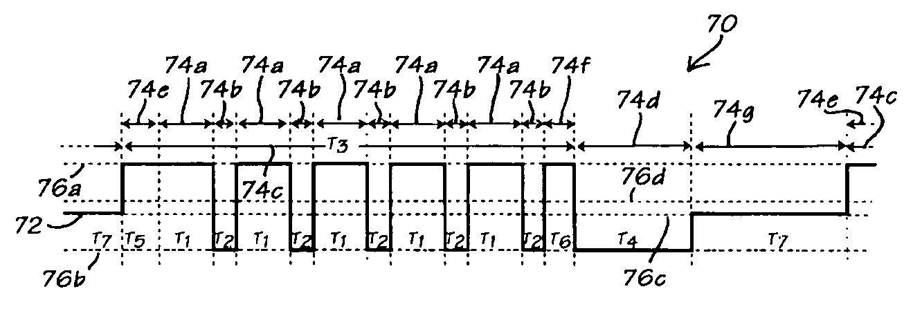
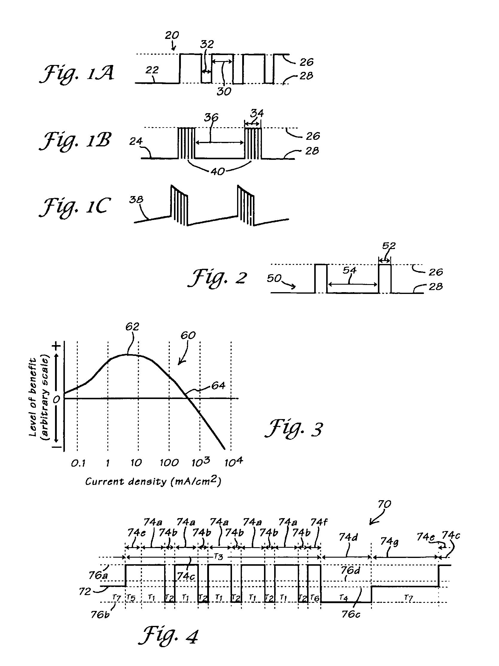
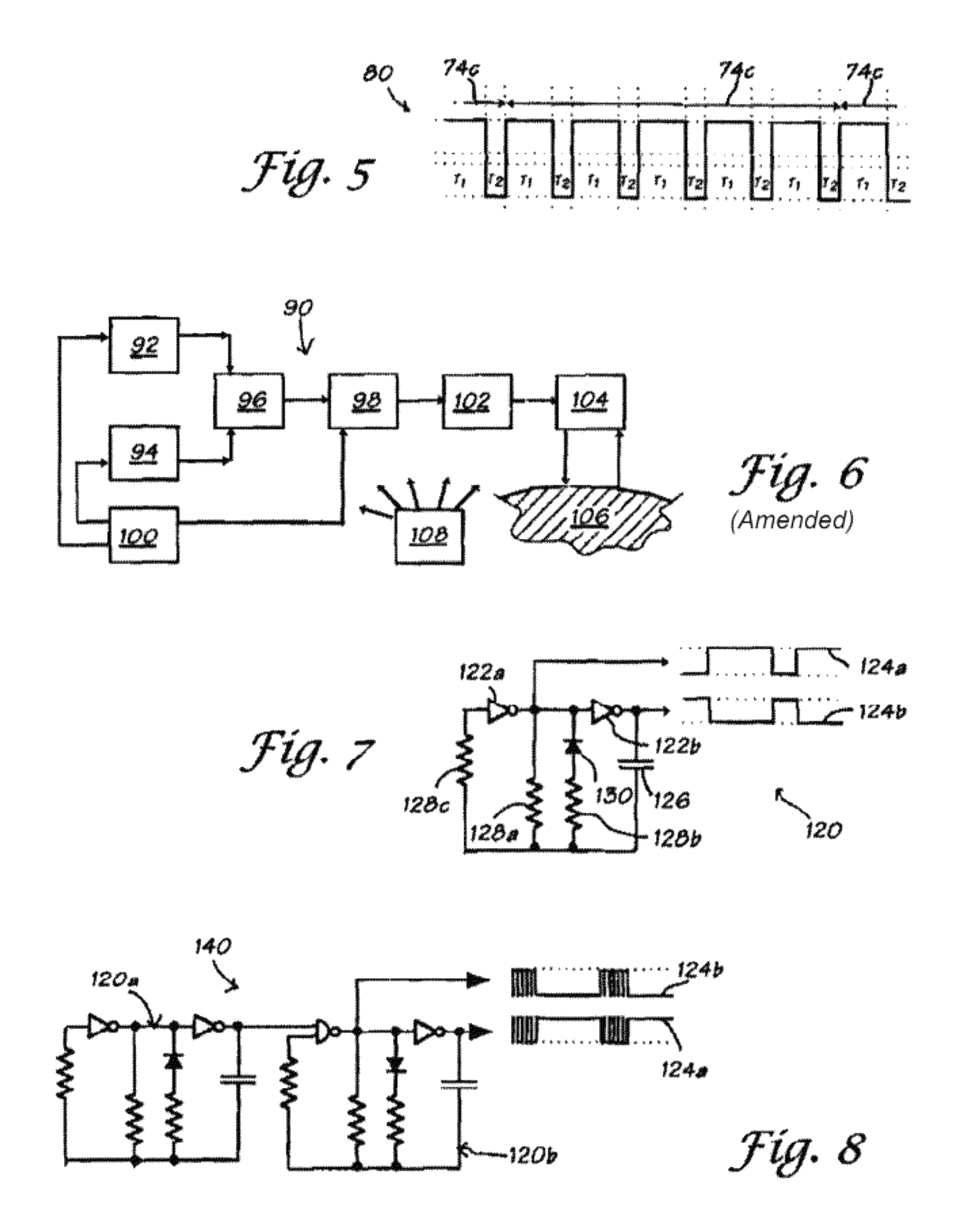
[0077]The present invention is an apparatus for use in providing bioelectric stimu...


PUM


Abstract

An apparatus for generating an electrical signal for use in biomedical applications, including two timing blocks for generating timing intervals T1-T7, an interconnection block for combining these intervals into an output signal having predetermined relationships among the intervals, an output block for transmitting the output signal to a load, and, optionally, a filter for removing unwanted frequency components from the output signal and an adjustment block for selecting from among a plurality of output signals with predetermined characteristics. The output is a repeating succession of a burst of rectangular waves, an equalizing pulse (if needed) to cancel net DC, and a rest period of no signal.

Description

BACKGROUND OF THE INVENTION[0001]1. Field of the Invention[0002]The present invention relates to a pulsed signal generator for biomedical applications. In particular, the present invention relates to a light-weight, compact pulsed signal generator that produces an output waveform based on at least four timing intervals T1-T4, more preferably, a waveform based on seven timing intervals T1-T7.[0003]2. Discussion of Background[0004]Injuries, infections and degenerative conditions are major sources of pain, inconvenience, expense, lost work (and leisure) time and diminished productivity. The problems associated with these conditions grow worse with age, since an injury which would heal quickly in a young, healthy person takes much longer in one who is older, in poor health, or both. In demographically-aging societies such as now seen in most of the industrialized nations, these social and economic impacts will become increasingly magnified over the course of the next several decades.[00...

Claims


Application Information

Patent Timeline
IPC IPC(8): A61N1/34A61N1/32
CPCA61N1/326A61N1/36021A61N1/36071A61N1/36178
Inventor KRONBERG, JAMES W.
Owner MEDRELIEF
Learn More