Intake valve timing in multi-valve, camless engines

a technology of camless and intake valve, which is applied in the direction of machines/engines, non-mechanical valves, output power, etc., can solve the problems of reducing the maximum power output of the engine, and achieve the effect of improving the combustion system of the engine, reducing the maximum output power of the engine, and high turbulence flow field

Inactive Publication Date: 2011-09-06
FORD GLOBAL TECH LLC
View PDF12 Cites 5 Cited by
  • Summary
  • Abstract
  • Description
  • Claims
  • Application Information

AI Technical Summary

Benefits of technology

[0006]It is an advantage of the present invention to provide an improved combustion system for an engine.

Problems solved by technology

However, the tumble and / or swirl generation often comes at the expense of discharge coefficient, thus reducing the maximum power output of the engine.

Method used


Image

  • Intake valve timing in multi-valve, camless engines
  • Intake valve timing in multi-valve, camless engines
  • Intake valve timing in multi-valve, camless engines

Examples


Embodiment Construction

)

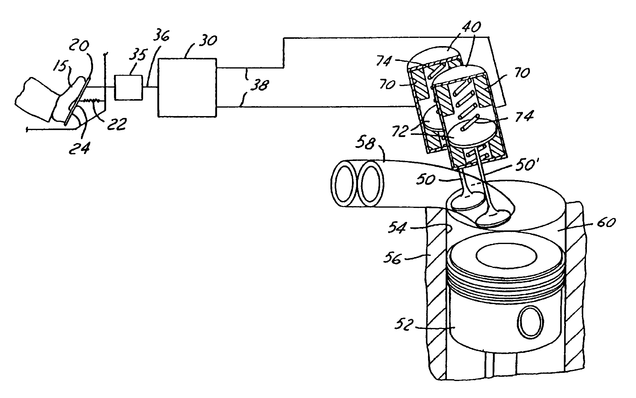
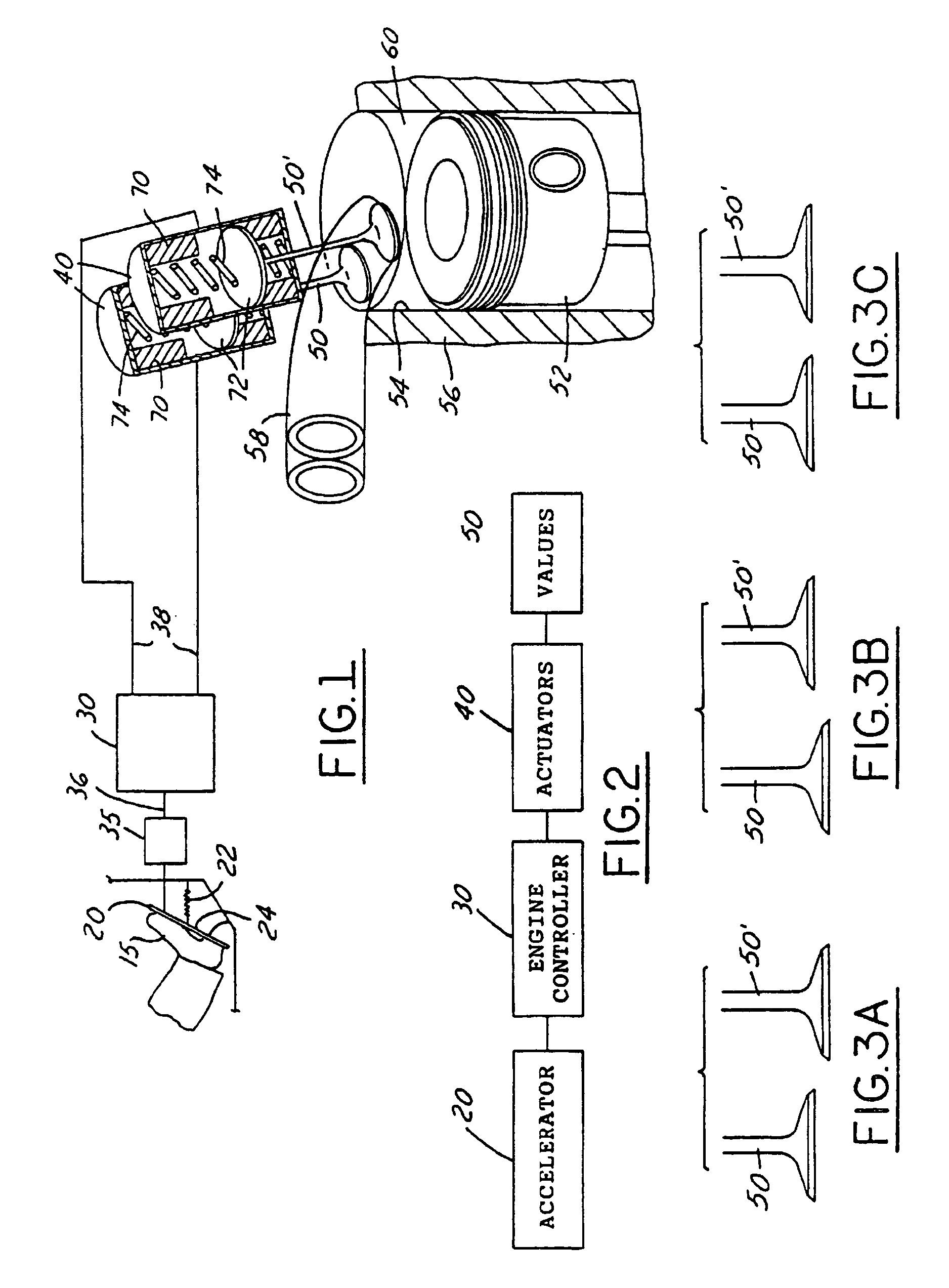
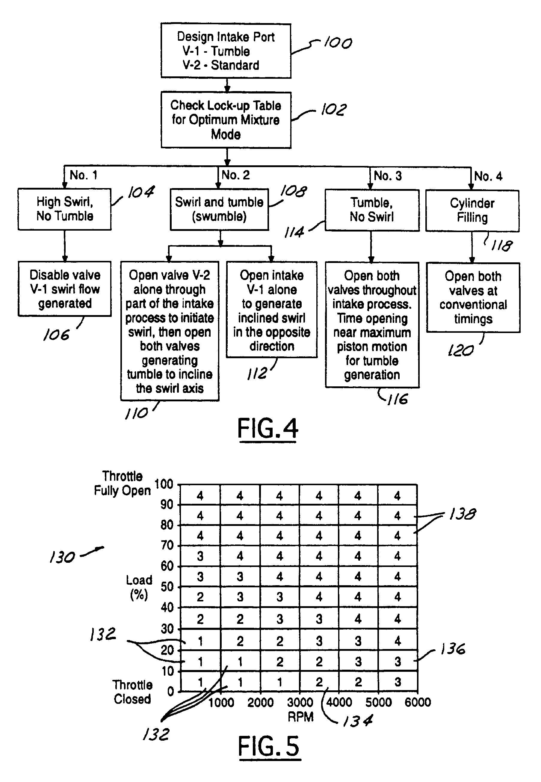
[0017]The formation of swirl or tumble motion of air / fuel mixtures in combustion chambers is important for increasing the burn rate of the fuel in spark ignited engines. In tumble, the inducted air rotates about an axis perpendicular to the axis of the cylinder. Swirling air flow motion has its axis of rotation parallel to the cylinder axis. Finally, the word “swumble” denotes in-cylinder flow motion with an axis of rotation inclined relative to the cylinder axis.

[0018]In many cases, the generation of the tumble and / or swirl flows of air comes at the expense of reducing the discharge coefficient of the flow through the valve by masks or other obstructions to flow being placed in the vicinity of the valve opening. Thus, the power output of the engine is reduced or degraded. The present invention generates high swirl and tumble air flows by delaying or advancing the opening of one intake valve relative to the other in the multi-valve engine and does not degrade the discharge coeffici...


PUM


Abstract

Two intake valves are independently operated by electromechanical actuators and activated by the engine electronic controller. One tumble-type intake valve and one conventional intake valve are provided in each cylinder. The valve members are individually opened and closed to achieve a desired air flow pattern in the combustion chamber to optimize combustion which increases fuel economy and reduces undesirable emissions. The opening and closing of the valve members depends on the engine speed, engine load, and other factors.

Description

CROSS REFERENCE TO RELATED APPLICATION[0001]This application is a divisional of reissue application Ser. No. 11 / 119,496, filed Apr. 28, 2005, which is a reissue of U.S. Pat. No. 6,553,961, which was filed Dec. 5, 2000, and issued Apr. 29, 2003.TECHNICAL FIELD[0002]The present invention relates to intake valve systems for multi-valve engines, and more particularly to methods and apparatus for securing desired air-fuel mixture turbulence level in the combustion chamber in order to achieve optimum combustion.BACKGROUND[0003]It is a common goal with vehicle manufacturers today to provide engine and combustion systems which improve fuel economy and, at the same time, reduce undesirable emissions. There are many systems which have been developed which accomplish one or more of these goals and achieve satisfactory results. Some of these systems include, for example, supplying prespecified amounts of fuel and air during certain engine operating conditions, various combustion chamber configu...

Claims


Application Information

Patent Timeline
IPC IPC(8): F02B31/00F01L1/00F01L9/10F01L9/20F01L13/00F02D13/02
CPCF01L13/0005F01L2800/00F02B31/00F02D13/0234F02D13/0253F02D13/0257Y02T10/12F01L9/10F01L9/20
Inventor HAMMOUD, MAZENHAGHGOOIE, MOHAMMAD
Owner FORD GLOBAL TECH LLC
Why Eureka
Try Eureka