
Method for producing a shielding case

a shielding case and shielding technology, applied in the direction of manual label dispensers, lamination, coatings, etc., can solve the problems of limited mechanical properties, high conductivity, difficult to achieve the optimal compromise between high elasticity, high conductivity and lowest possible material cost, and difficult to achieve the optimal compromise between high elasticity, high conductivity and low material cost. , to achieve the effect of shielding even gaps, reducing the deformation and elastic return force of the profile section, and reducing the deformation

Inactive Publication Date: 2010-10-26
TIBURTIUS BERND +1
View PDF34 Cites 0 Cited by
  • Summary
  • Abstract
  • Description
  • Claims
  • Application Information

AI Technical Summary

Benefits of technology

[0010]The object of the present invention is to provide a method of producing a shielding casing of the kind set forth in the opening part of this specification, which permits simple and inexpensive production of shielding casings with very good mechanical and electromagnetic properties and with a long service life.
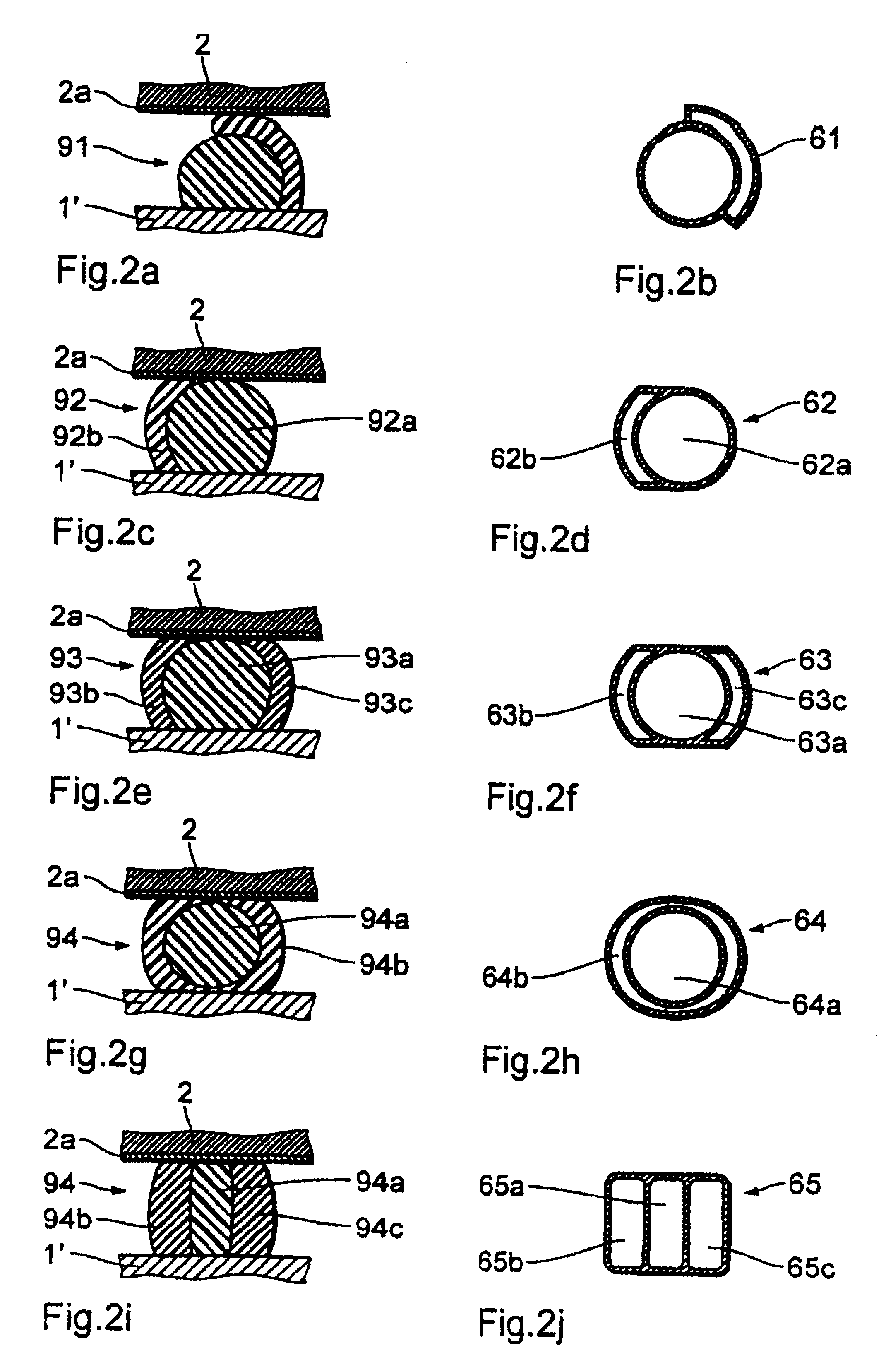
[0013]The profile portion or section formed from the first material primarily involves the function of filling the gap space in order in spite of mechanical play in respect of the casing portions, which is caused by production tolerances or surface irregularities, to reliably protect the interior of the casing from moisture and dust and possibly prevent relative movements between the casing portions. By virtue of the mechanically optimised properties of the first material it is possible for the internal space in the casing to be durably hermetically sealed off. At the same time the first profile section is naturally a carrier for a section of the electromagnetic shielding and ensures the closure integrity thereof. In regard thereto it is particularly advantageous to adopt a material with a high level of elasticity and / or a configuration for the seal which affords elasticity in respect of shape, on the basis of which upon assembly of the casing portions compression and / or flexion of the sealing element affords a prestressing effect as between the casing portions which for example can prevent a screw or clamping connection from coming loose.
[0015]Production of the shielding profile section is advantageously technologically simplified and rendered less expensive by virtue of the use of a plastic material which hardens in air and at ambient temperature and which in particular has thixotropic properties, more specifically on a silicone basis, but alternatively it is also possible to use heat-hardening or radiation-crosslinking material.
[0016]To achieve a shielding effect which satisfies the high test requirements involved, the electrically conductive inclusions added are especially particles comprising a metal or an alloy with a high level of electrical conductivity, in particular silver or a silver-bearing alloy. What is less expensive is the use of a silver-coated powder comprising another metal (nickel, copper or the like) or non-conducting carrier particles (for example of glass). The metal content is typically over 25% by mass, or to achieve very high shielding effects in relation to mobile telephones etc possibly even markedly over 50% by mass, with respect to the mass of the silicone-metal mix.
[0017]Besides metal powder, it is also possible in particular to use short metal fibres or metal flakes which in the plastic matrix, if their dimensions are suitably adapted to match the properties of the matrix material and the method characteristics, can advantageously form a kind of metal lattice structure This can impart to the conductive profile portion a high level of conductivity with a relatively small proportion of metal and in conjunction therewith can at the same time afford advantages in terms of relatively low hardness and brittleness.
[0025]The degree of deformation of an approximately U-shaped two-component sealing and shielding profile section of solid material can be (relative to the height of the unloaded profile section) 30% or more, and for certain uses preferably up to over 50%. By virtue of special profile cross-sectional configurations, for example the adoption of a lip profile which is at the same time compressible and flexurally deformable, it is possible to additionally deliberately and specifically influence an effective degree of deformation and elastic return force of the profile section. The specified method steps and possibly additional geometrical measures make it possible to reliably shieldingly seal even gaps of a width which differs considerably over the longitudinal extent thereof. This permits greater tolerances in the prefabrication of the casing portions, in such a way as to reduce costs.

Problems solved by technology

In production of a material for the shielding seal however it was found that it was difficult to arrive at an optimum compromise between high elasticity, high conductivity and lowest possible material costs.
A material with an advantageously high shielding action is a plastic material which is filled with a high proportion of silver powder but this is relatively expensive and has only limitedly satisfactory mechanical properties DE39 34 845 A1 describes the production of a shielding casing with a two-layer shielding profile by the application of an elastic but non-conductive sealing profile to a casing portion and then spraying a conductive coating on to that sealing portion.
This method basically makes it possible to save on material costs but it is technologically complicated and expensive and results in seals whose mechanical and in particular electromagnetic properties cannot be completely convincing.

Method used


Image

  • Method for producing a shielding case
  • Method for producing a shielding case
  • Method for producing a shielding case

Examples


Embodiment Construction

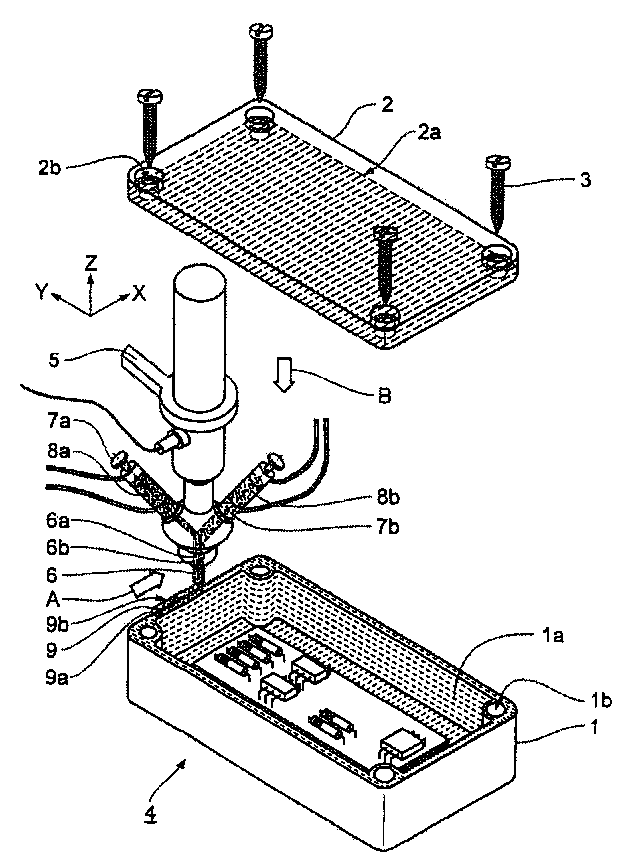
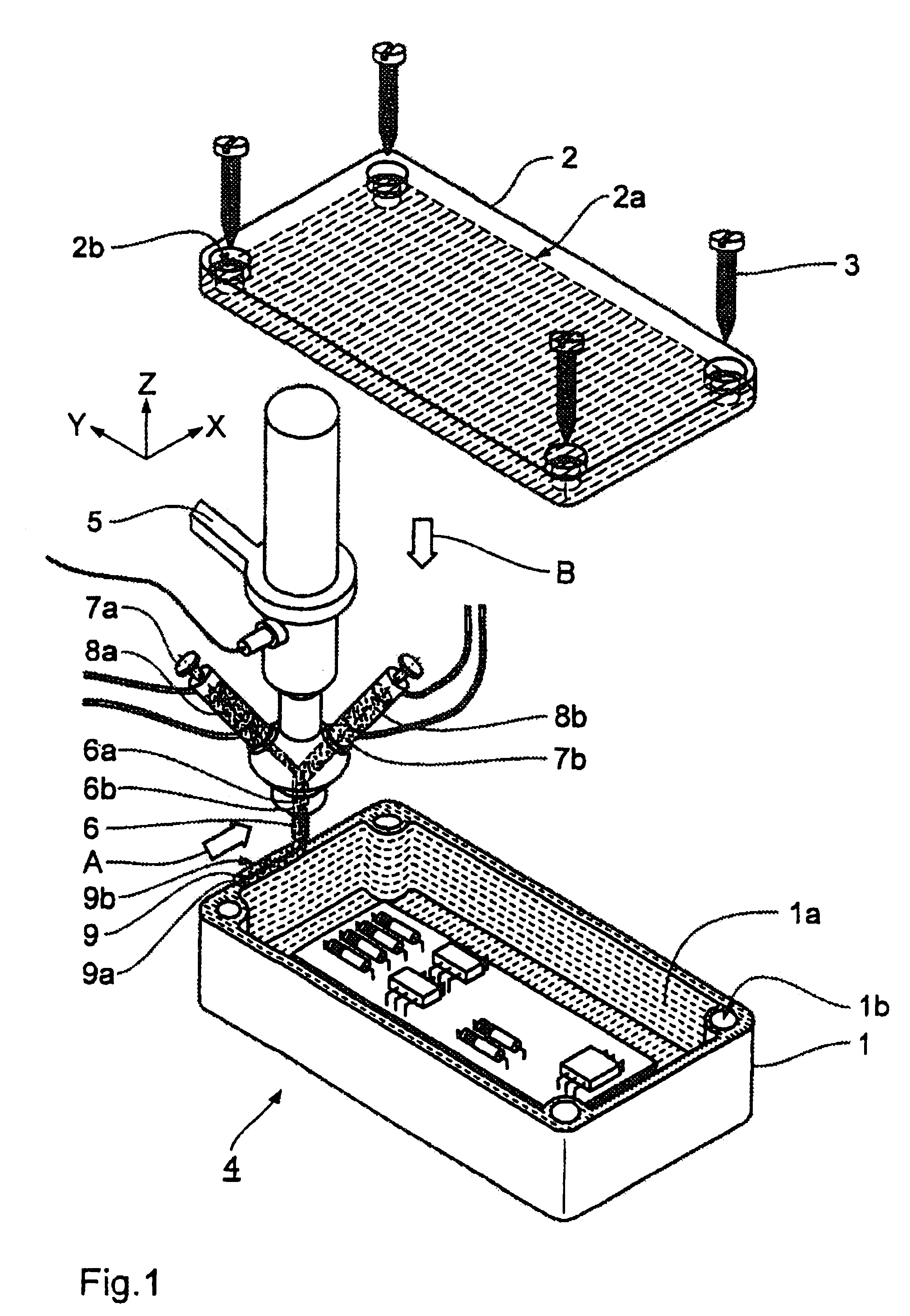
[0029]FIG. 1 is a diagrammatic view showing the principle of a casing bottom portion 1 and a casing cover 2 of injection-moulded plastic material for an electronic device (in practice for example a mobile telephone), which are both provided with an inside metallisation layer 1a and 2a respectively. Formed in both casing portions 1, 2 are screw holes 1b and 2b respectively. wWherein the screw holes 1b in the casing bottom portion are provided for partially self-tappingly screwing in self-tapping screws 3 while the screw holes 2b in the cover each have a countersink for accommodating the screw head of the respective screws 3. This screw connection permits the device casing 4 to be opened and re-closed repeatedly if required.

[0030]The Figure diagrammatically shows the way in which an arm 5 of a coordinate-controlled handling device (not shown overall as such) guides an applicator needle 6 having two concentrically extending passages or ducts 6a, 6b, with hose connections 7a, 7b for fee...


PUM

PropertyMeasurementUnit
Temperatureaaaaaaaaaa
Thicknessaaaaaaaaaa
Electrical conductivityaaaaaaaaaa

Abstract

Method of producing a shielding casing (4) in which there is provided a sealing and shielding profile section (9) which fills a gap between first and second adjoining casing portions (1, 2) and which comprising pasty material is applied under pressure from a coordinate-controlled applicator device (5) having an applicator needle or nozzle directly on toonto the first casing portion and then sets there elastically adhering thereto in self-supporting relationship, wherein the sealing and shielding profile section is produced by simultaneously applying at least one first material (8a) with material properties adapted for a good sealing action and a second material (8b) with material properties adapted to a good shielding action, from the applicator needle or nozzle (6) provided with at least a first and a second passage (6a, 6b), whereby the second material firmly adheres to the first material.

Description

[0001]The subject application is a Continuation Reissue application Ser. No. 12 / 111,943 filed Apr. 29, 2008 of U.S. Reissue patent application Ser. No. 10 / 702,054 ('054 Reissue Application) filed Nov. 5, 2003, which is a reissue application of U.S. Pat. No. 6,312,550('550 Patent) issued Nov. 6, 2001 and filed as a National Stage application of International Application PCT / DE98 / 00682(PCT '682 application) claiming priority of DE 197135242 filed Mar. 5, 1997. <?insert-end id="INS-S-00002" ?>BACKGROUND OF THE INVENTION[0002]Electrically shielding casings for accommodating and electromagnetically shielding units which emit electromagnetic radiation or which are sensitive to electromagnetic radiation have long been known.[0003]While earlier such casings were usually made from metal for obvious reasons, with the onset of the spread thereof on a large scale—for example in relation to mobile telephones or cordless telephones—for cost and weight reasons there has been a change over to...

Claims


Application Information

Patent Timeline
IPC IPC(8): B05D5/10B05D5/12H05K9/00
CPCH05K9/0015Y10T156/1798H05K9/00
Inventor TIBURTIUS, BERNDKAHL, HELMUT
Owner TIBURTIUS BERND
Learn More