In the liquid crystal
display device of the present invention, the terminals of the video
signal lines are extracted to only one side of the liquid crystal display panel, and the video
signal line
driving circuit substrate to be connected with the terminals is arranged at the side of the display panel, usually at only one longer side. As a result, the area of the frame portion around the display unit can be reduced to reduce the size and weight of the liquid crystal display device and the data
processing device assembling the former. Moreover, when the liquid crystal display device is packaged as the display unit in the data
processing device such as a
personal computer or word processor, the side, at which the video signal line
driving circuit substrate is arranged, is located at the upper side of the display. In the notebook type
personal computer or word processor having the display unit hinged to the keyboard portion, a space for attaching the hinges to the lower portion of the display can be easily retained to make the vertical position of the display proper.
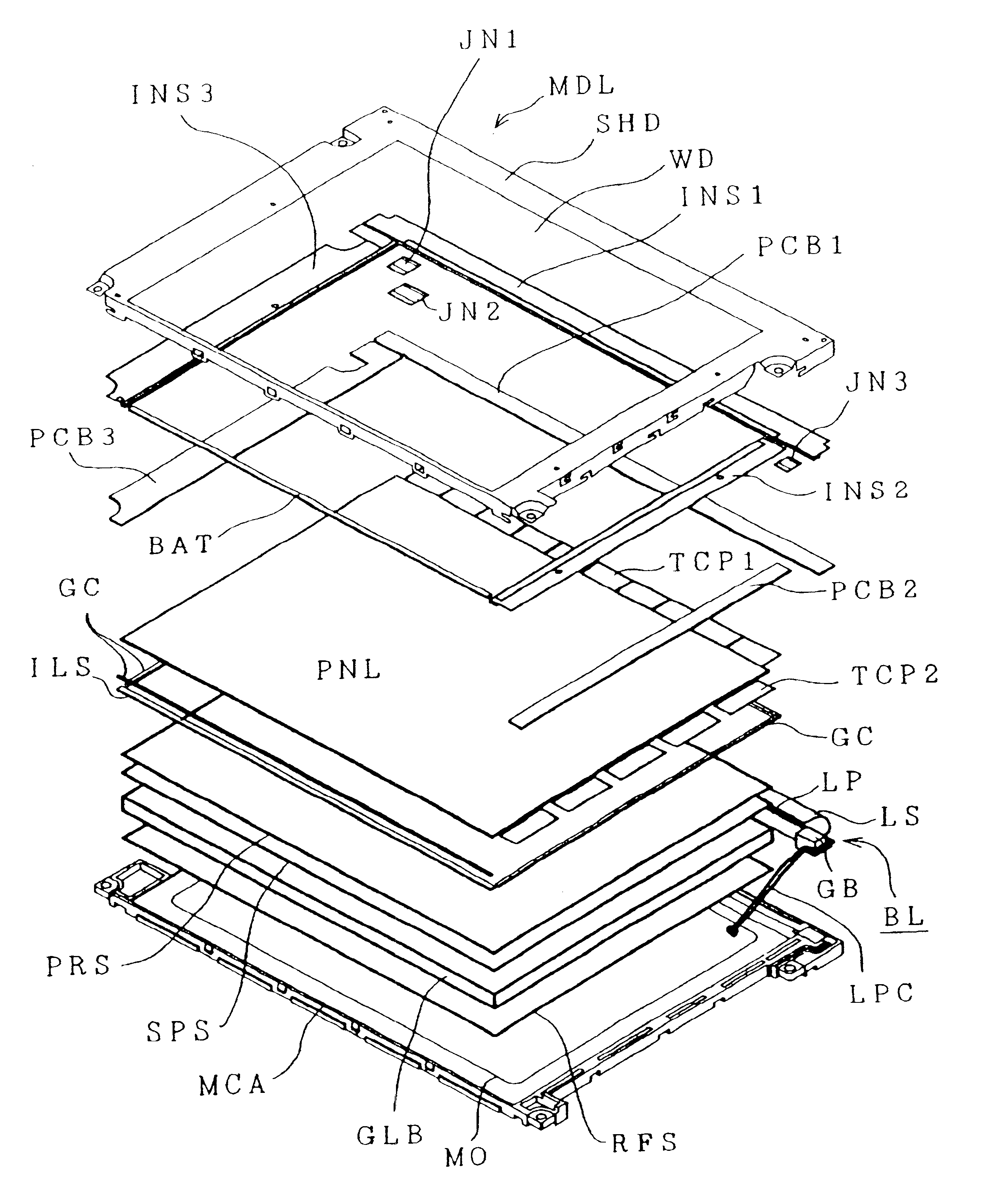
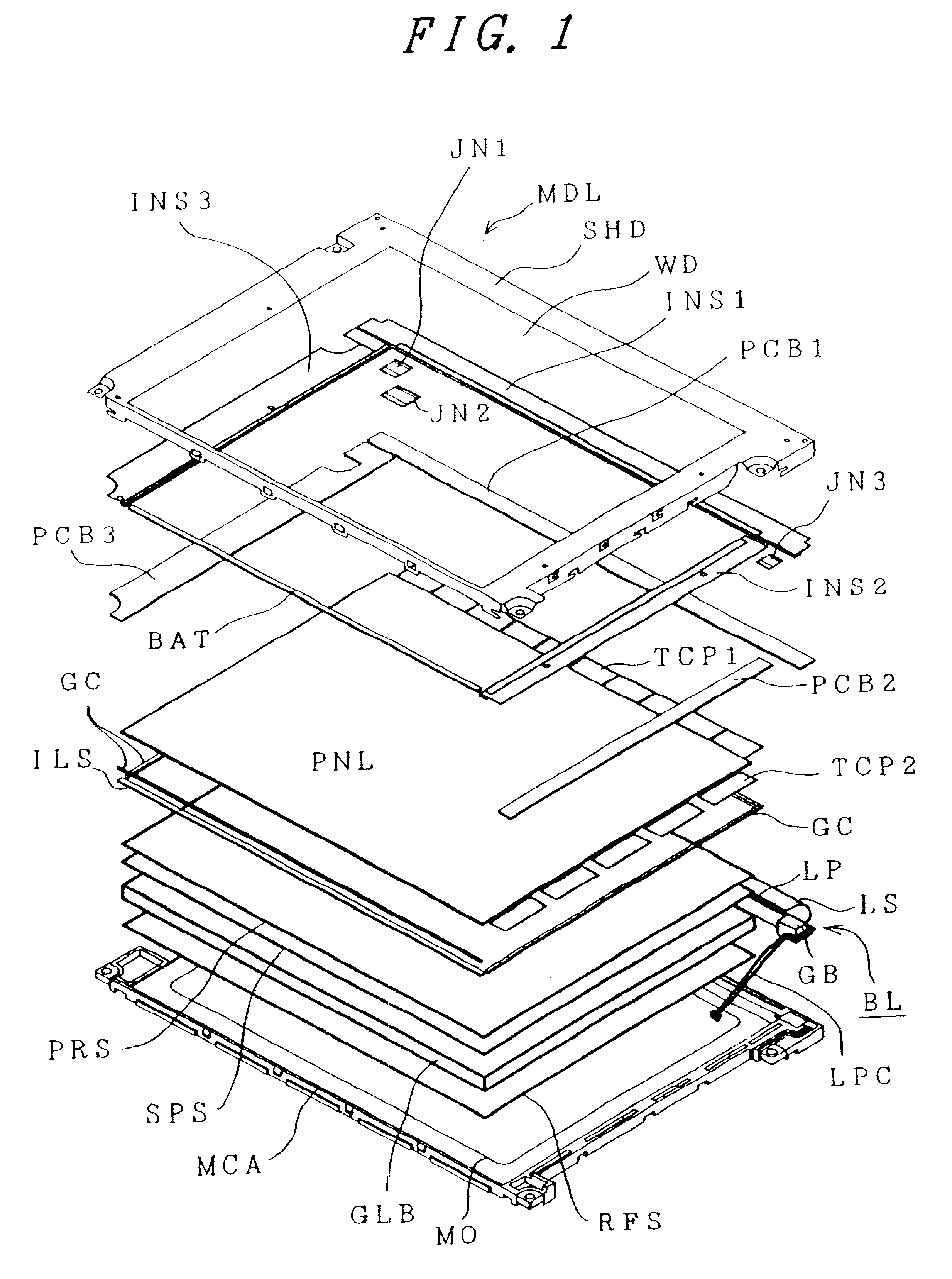
In the liquid crystal display device of the present invention, moreover, one of the two insulating substrates constituting the liquid crystal display panel is protruded and formed with the
single plate portion and is exclusively held through the elastic member mounted on the
single plate portion, so that the gap between the two substrates is not changed to cause no display unevenness even if strongly pushed. As a result, the pushing force of the liquid crystal display panel can be increased to improve the
mechanical strength and the reliability.
In the liquid crystal display device of the present invention, moreover, the slender fluorescent tube is arranged in the space below the plurality of tape carrier packages packaged on the outer
peripheral portion of the liquid crystal display panel so that it can be accommodated in a high space using efficiency. As a result, the device can have its external size reduced to reduce the size and the weight.
In the liquid crystal display device of the present invention, moreover, the size of the
light guide plate of the back light is made as small as that of the effective light emitting unit so that the electronic parts can be packaged in the space which has been occupied by the light guide plate of the prior art. At the same time, the light guide plate is held by the small projections formed on the inner face of the casing accommodating the light guide plate so that the light guide plate can be held in the small space. As a result, the device can be small-sized and light-weighted to reduce the production cost.
In the liquid crystal display device of the present invention, moreover, a large opening is formed in the bottom face of the mold casing at a central portion other than the surrounding frame portion so that the bottom face of the mold casing can be prevented, by the weight and
internal pressure of the liquid crystal display panel, after the
assembly of the liquid crystal display device, from being bulging out by the force to be applied vertically downward to the bottom face of the mold casing. As a result, the mold casing can be thinned to reduce the thickness and weight of the liquid crystal display device.
In the liquid crystal display device of the present invention, moreover, the two cables, as connected with the two ends of the fluorescent tube of the back light, are fitted in the groove formed in the casing, and the
inverter is accommodated in the accommodating portion formed in the mold casing outside of the light guide plate, so that the cables and the
inverter can be accommodated without bulging out of the device. As a result, the liquid crystal display device can be small-sized and light-weighted to reduced the production cost.
In the liquid crystal display device of the present invention, moreover, a notch is formed in the casing at a portion corresponding to the exothermic portion. As a result, it is possible to provide a liquid crystal display device having such a circuit as can improve not only the heat liberation of the exothermic portions, the highly dense packageability of the circuit and the compactness and as can realize the multi-
gradation, the single power source and the compact packaging.
In the liquid crystal display device of the present invention, moreover, the
hybrid integrated circuit, as prepared by hybridly integrating a portion of the circuit for driving the liquid crystal display panel, is packaged on the circuit substrate so that the number of the electronic parts can be reduced. At the same time, neither another circuit substrate nor any joiner is required, it is possible to reduce the cost for the material and the number of working steps. As a result, the production cost can be reduced to improve the reliability of the product.
In the liquid crystal display device of the present invention, moreover, by positioning the mounting holes of the casing away from the case corners, the space for electrically connecting the circuit substrate by the joiners can be retained while being left generally rectangular, so that the extraction efficiency of the circuit substrates can be made high to reduce the cost for the material of the circuit substrates.
In the liquid crystal display device of the present invention, moreover, the space of the device in the thickness direction can be effectively exploited to electrically connect the plurality of circuit substrates by two or more electric connection means superposed at two or more stages. As a result, the circuit substrates can be connected in a small space, even if the number of their connection lines is large, to reduce the size and weight of the liquid crystal display device.
In the liquid crystal display device of the present invention, moreover, the mounting holes can be formed, if intended so, in the intermediate portions at a predetermined considerable distance from the corners of the metallic casing by
notching the radial portion of a quadrant between the drawn portions to be formed with the mounting holes and the
metal plate adjacent to the former, to draw the drawn portions generally into the quadrant. As a result, the liquid crystal display device can be small-sized and light-weighted.
In the liquid crystal display device of the present invention, moreover, the pawls, as integrally formed by
notching the metallic shield casing, are connected with the frame ground pads which are connected with the ground wiring lines and formed on the face of the circuit substrate. As a result, the ground wiring lines are connected with the common metallic shield casing having a sufficiently
low impedance so that the they are strengthened in a higher frequency range to suppress the emission of the harmful radiative electric
waves.
In the liquid crystal display device of the present invention, moreover, the mounting holes can be formed, if intended so, in the intermediate portions at a predetermined considerable distance from the corners of the metallic casing by
notching the radial portion of a quadrant between the drawn portions to be formed with the mounting holes and the
metal plate adjacent to the former, to draw the drawn portions generally into the quadrant. As a result, the liquid crystal display device can be small-sized and light-weighted.
In the liquid crystal display device of the present invention, moreover, the electronic parts of the
signal source integrated circuit, as have a low level, are arranged at the remotest end of the circuit substrate having the connector with the outside, that is, over the circuit substrate in the vicinity of the corner of the casing for accommodating the circuit substrate and the liquid crystal display panel, and the connector is arranged adjacent thereto in the direction apart from the corner. As a result, the vicinity of the corner of the casing, as formed with the mounting holes, can be covered with the case integral with or separate from the aforementioned casing. When the device is packaged in the data
processing device such as a personal computer, the corner of the casing of the device is firmly held and fixed through the mounting holes by the screws or the like so that the mechanically strength can be improved to improve the reliability of the product.
In the liquid crystal display device of the present invention, moreover, a plurality of electronic parts for counter-measures of the EMI are arranged concentratedly on the circuit substrate so that the
dead space can be reduced to
package the electronic parts highly densely. As a result, the liquid crystal display device can be small-sized and light-weighted to reduce the production cost.

