Method for receiving and transmitting optical data and control information to and from remotely located receivers and transmitters in an optical locator system

a technology of optical locator and optical data, applied in the field of position locating system, can solve the problems of only marginally useful signal strength, continuous power consumption, and random reflections introducing interference and path distortion in tag transmission, etc., and achieve the effect of easy entry and chang

Inactive Publication Date: 2000-01-25
FRESHLOC TECH
View PDF20 Cites 37 Cited by
  • Summary
  • Abstract
  • Description
  • Claims
  • Application Information

AI Technical Summary

Benefits of technology

The present invention is a method for receiving and transmitting optical data and control information to and from remotely located receivers audio transmitters in an optical locator system. Also, the present invention does not rely on hard-wired, or permanently programmed information stored within any of its transmitters that provide the locator system with identifying information. Data and control information can readily be entered and changed using the present invention.
The TAG selects a maximum number of transmissions from the TAG to the optical system. The TAG then selects a time delay that restricts the transmissions from the TAG to the optical system to that selected maximum number. The TAG's sleep mode is then activated, thereby reducing the normal electrical power consumption by the TAG. The TAG selectively predetermines a terminal time interval for the sleep mode. The terminal time interval ranges up to 3600 seconds and commences when the TAG enters the sleep mode. The sleep mode is reactivated by the TAG when the selected time delay added to the total sleep mode time is greater than the selected terminal time interval, thereby the TAG returns the power level to its normal level. The TAG then forms an uplink information package containing the information packets and then the TAG will transmit that package to the optical locating system. If desired, the TAG will check the battery life and transmit that status along with the information package of the uplink transmission. Then the TAG activates the sleep mode until the next total sleep mode time plus selected time delay is greater than the selected terminal time interval.
In the preferred embodiment of the present invention the TAG selects a motion count to define the number of allowable motion detections or desired motion detections. The TAG activates the sleep anode, thereby reducing it's normal power consumption. The TAG will reactivate the sleep mode when motion is detected by the motion detector, thereby returning the power level of the TAG to normal. The TAG will select a wrappable transmission interval count defining the number of transmissions to the optical locator system. This particular count is wrappable and inclementable, i.e. if the counter normally counts from 1 to 9, the counter when reaching 9 will start over with 1. This type of counter is defined to be wrappable. The wrappable counter used in the present invention is not limited to a count or 1 to 9. In fact, any wrappable counter may be used with the present invention. Once the selection is made, the TAG will form an uplink information package containing at least one information packet, checked battery life and a transmission interval count. The TAG will then transmit the uplink information package to the optical locator system. The TAG will randomize a preselected time delay for offsetting the uplink transmission, thereby preventing interference from other TAGs within range of the transmitting TAG. The motion count is then decremented thereby reducing the number of allowable motion detections. The transmission interval count is then incremented thereby defining the next uplink transmission from the previous uplink transmission. The TAG will continue transmitting uplink packages at selected intervals as long as the motion count is true. When the motion count is false, the TAG will stop transmitting and activate the sleep mode, thereby reducing electrical power consumption by the TAG.

Problems solved by technology

However, a problem with radio communications in a typical business environment, which includes walls, windows and other fixed structures, is that for the frequency of interest (i.e., above 100 MHz), random reflections introduce interference and path distortions in TAG transmissions arriving at a given receiver.
Moreover, in such an environment, the unpredictable continuation of transmissions through walls and other structures make signal strength only marginally useful for communicating distance and location information.
Since the transceiver awaits scanning, power consumption is continuous.
Utilizing the scan response transmission format may result in transceivers not transmitting because they are in a dead zone, i.e., transceivers out of range of the scanning transceiver.
This inability to receive signals during a scan cycle will result in a "temporary lost personnel" status being transmitted to the personnel locator system.
Additionally, since the distance from the transceiver unit to the remote transceiver location is variable, the transceiver design must accommodate worse case transmission ranges at the expense of additional power requirements.
Another problem that exists with ultrasonic personnel locating systems is due to their susceptibility to heavy ultrasonic noise.
In most factory applications, there is a heavy ultrasonic background noise that interferes with the operation of the ultrasonic personnel locating systems.
These reflected signals provide interference signals.
Since ultrasonic signals travel only at the speed of sound, the longer propagation delay of the reflected signals produce a more troublesome interference signal.
However, this approach usually results in the personnel locator system reporting the "temporary lost personnel" for users who have simply forgotten to turn on their TAG when entering a room that has a TAG receiver.

Method used


Image

  • Method for receiving and transmitting optical data and control information to and from remotely located receivers and transmitters in an optical locator system
  • Method for receiving and transmitting optical data and control information to and from remotely located receivers and transmitters in an optical locator system
  • Method for receiving and transmitting optical data and control information to and from remotely located receivers and transmitters in an optical locator system

Examples


Embodiment Construction

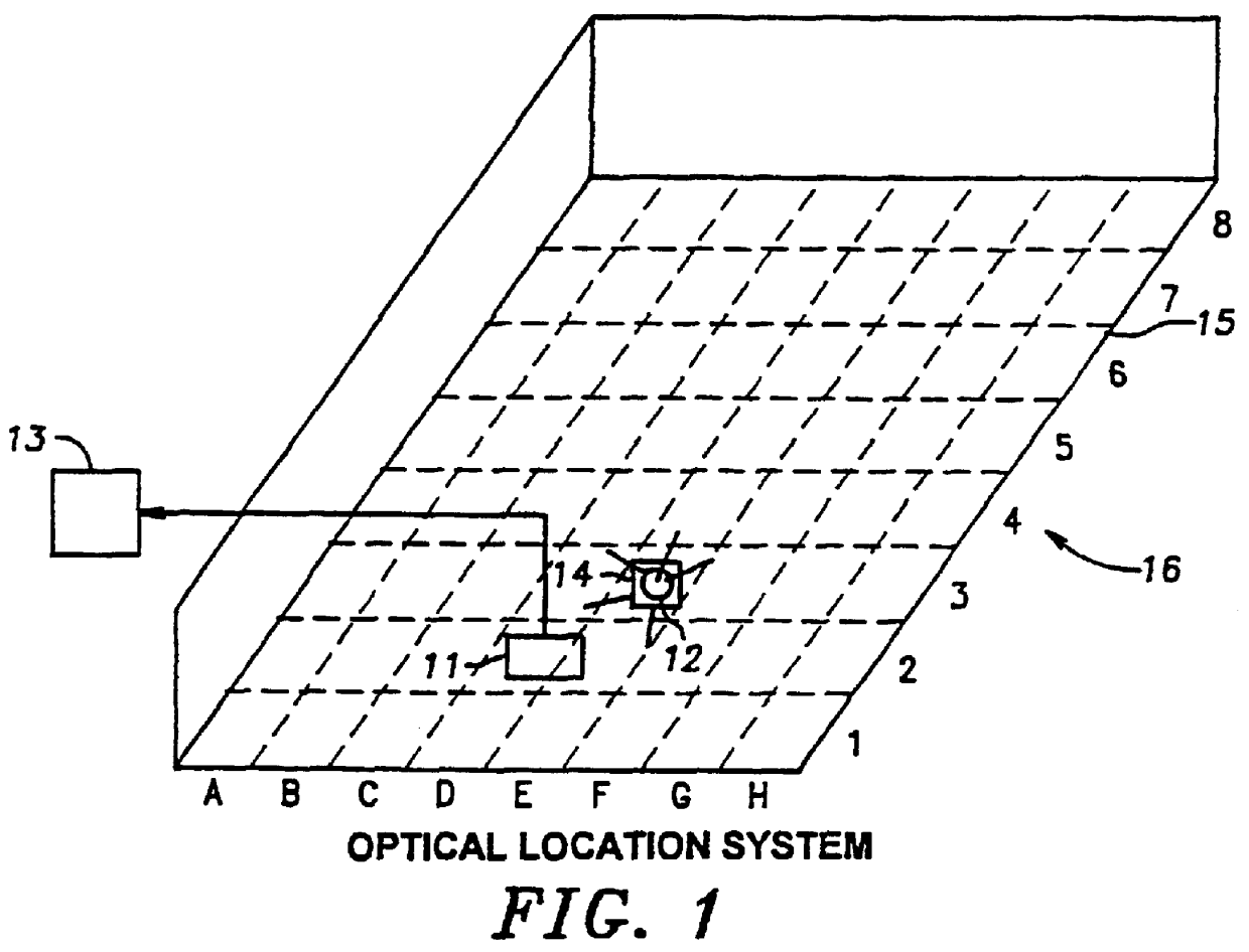
An optical location system is generally shown at 16 in FIG. 1. That system comprises essentially of a transceiver 11 cooperating with processing station 13 and transceiver 12 which is attached to target 14. Albeit, the optical location system 16 is shown having only transceivers 11 and 12. The optical system may have a plurality of transceivers but for the purposes of this discussion the optical system will only have transceivers 11 and 12. If desired, transceivers 11 and / or 12 may be replaced by a separate receiver and transmitter contained in their respective packages. Transceiver 11 in conjunction with processing station 13 are used to locate target 14 moving within the defined area 15. For example, target 14 may be a box containing a work piece, such as a printed circuit board, which travels from one production station to another in a manufacturing plant during assembly. The system of FIG. 1 is a two-dimensional positional location system, in that the positioning is determined i...


PUM


Abstract

The method for receiving and transmitting optical data and control information to and from remotely located receivers and transmitters in an optical location system. Wherein, the locator system tracks and locates the position of a main object having an attached transceiver. This transceiver has stored in memory selected identifying information about the object to which the transceiver is attached. The selected identifying information was received by the transceiver over it's 1-wire interface from a touch memory.

Description

FIELD OF THE INVENTIONThe invention relates generally to a position locating system, in particular an optical locator system adapted for use in an environment subject to optical transmission interference. In greater particularity, the invention relates to a system that accomplishes position location using area detection receivers that receive optical transmissions from a remotely located transmitter. In even greater particularity, the invention relates to portable optical transmitters that receive encoded digital information and retransmits that information by optical means.BACKGROUND OF THE INVENTIONPosition or object location systems are finding increasing application in manufacturing and materials handling environment. For example, such systems have utility for factory automation, including such application as tool automation, process control, robotics, computer integrated manufacturing (CIM), and just in time (JIT) inventory control.One approach to position location systems is t...

Claims


Application Information

Patent Timeline
IPC IPC(8): G07C9/00G06K7/10G06K7/00G08B3/10
CPCG06K7/0008G06K7/1097G07C9/00111G08B3/1083G07C9/28
Inventor HELLER, ALAN C.FOX, CHRISTOPHER W.
Owner FRESHLOC TECH
Why Eureka
Try Eureka