Method for calculating interaction potential between filler particles in polymeric material

a polymer material and interaction potential technology, applied in the field of calculating the interaction potential between filler particles in polymeric materials, can solve the problem of difficulty in high-accuracy simulation, and achieve the effect of high accuracy

Active Publication Date: 2018-04-17
SUMITOMO RUBBER IND LTD
View PDF1 Cites 0 Cited by
  • Summary
  • Abstract
  • Description
  • Claims
  • Application Information

AI Technical Summary

Benefits of technology

[0016]In the present invention, therefore, the parameters of the Lennard-Jones potential can be determined based on the free energy in the virtual space. This is based on findings of the present inventor obtained through experiments, namely, the free energy in the virtual space calculated based on the mean field theory approximates the interaction potential between the filler models. Thus, the parameters can be determined without the need for human intuition and experience. As a result, it is possible to perform the simulation with high accuracy.

Problems solved by technology

Heretofore, the above-mentioned parameters σLJ and ϵLJ have been determined by an operator based on his / her intuition and experience, therefore, it is difficult to perform the simulation with high accuracy.

Method used


Image

  • Method for calculating interaction potential between filler particles in polymeric material
  • Method for calculating interaction potential between filler particles in polymeric material
  • Method for calculating interaction potential between filler particles in polymeric material

Examples


Embodiment Construction

[0035]Embodiments of the present invention will now be described in detail in conjunction with the accompanying drawings.

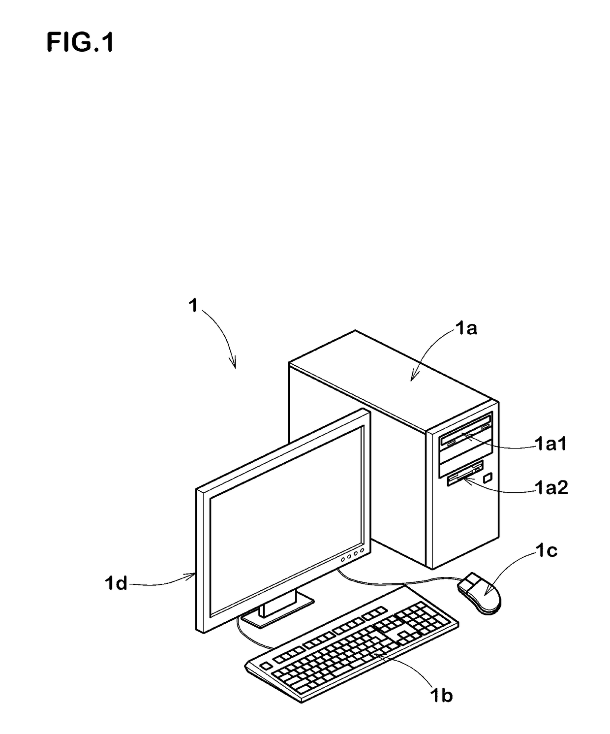
[0036]The method for calculating an interaction potential between filler particles in a polymeric material according to the present invention (abbreviated to “calculating method”) is carried out by the use of a computer 1.

[0037]Here, the filler may be any kind of filler including carbon black, silica, alumina and the like. The polymeric material may be any kind of polymer including rubber, elastomer, resin and the like.

[0038]As shown in FIG. 1 for example, the computer 1 implementing the calculating method comprises a main body 1a, a keyboard 1b, a mouse 1c and a display 1d. The main body 1a comprises an arithmetic processing unit (CPU), memory, storage devices such as magnetic disk, disk drives 1a1 and 1a2 and the like. In the storage device, programs / software for carrying out the calculating method is stored.

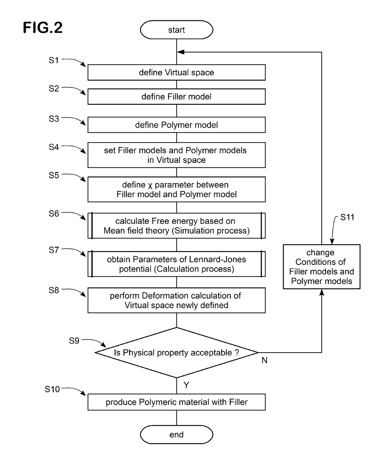
[0039]FIG. 2 shows a flow chart of the calculating met...


PUM


Abstract

A method for calculating an interaction potential between filler particles in a polymeric material by using a computer is disclosed. The method comprises: arranging filler models and polymer models in a virtual space; calculating a free energy in the virtual space based on a mean field theory; obtaining parameters of the Lennard-Jones potential by approximating the free energy to the Lennard-Jones potential.

Description

BACKGROUND OF THE INVENTION[0001]The present invention relates to a method for calculating an interaction potential between filler particles in a polymeric material, more particularly to a method for determining parameters of the Lennard-Jones potential between the filler particles.[0002]In recent years, in order to develop or design rubber compositions, various computer simulation methods for evaluating properties of a composite of a polymeric material and filler have been proposed.[0003]In such a simulation method, for example, filler models of filler particles are defined, and the Lennard-Jones potential ULJ given by the following equation (1) (namely, an interaction potential between two filler models) is defined between the filler models.[0004]ULJ⁡(rij)=4⁢ɛLJ⁢{(σLJrij)12-(σLJrij)6}Equation⁢⁢(1)wherein[0005]rij is the distance between two filler models,[0006]ϵLJ is a coefficient for the intensity of the potential between the filler models, and[0007]σLJ corresponds to the diamete...

Claims


Application Information

Patent Timeline
Patent Type & Authority Patents(United States)
IPC IPC(8): G06F17/50G06F19/00
CPCG06F17/5009G06F19/704G06F17/5018G16C20/30G06F30/23G06F30/20G06F30/25
Inventor UENO, SHINICHI
Owner SUMITOMO RUBBER IND LTD
Why Eureka
Try Eureka