Chain trap

a chain and trap technology, applied in the field of chain traps, can solve the problems of lack of safety mechanisms and inability to accommodate these spatial monstrosities in the home gym, and achieve the effect of reducing the generation of friction

Active Publication Date: 2018-04-10
JOHNSON JOEL ANTHONY
View PDF3 Cites 0 Cited by
  • Summary
  • Abstract
  • Description
  • Claims
  • Application Information

AI Technical Summary

Benefits of technology

[0004]The general purpose of the present invention, which will be described subsequently in greater detail, is to provide a chain trap that is capable of being attached to various bases and surfaces so as to allow the quick and simple connection of a chain of a linked construction.
[0006]In accordance with the invention, an object of the present invention is to provide an improved chain trap that is devoid of all moving parts and is capable of quick and secure affixation to a link of any compatibly sized chain.
[0009]It is a further object of this invention to provide an improved chain trap that allows for the passage of chain through its body with a minimum generation of friction.

Problems solved by technology

Most safety mechanisms are incorporated into the larger pieces of expensive and professional equipment.
Home gyms don't have the space to accommodate these spatial monstrosities, and thus lack these safety mechanisms.

Method used


Image

  • Chain trap
  • Chain trap
  • Chain trap

Examples


Embodiment Construction

[0029]As used herein, the term “chain” refers to a connected flexible series of links or rings (generally metal or steel) passing through one another, and used for fastening or securing objects and pulling or supporting loads.

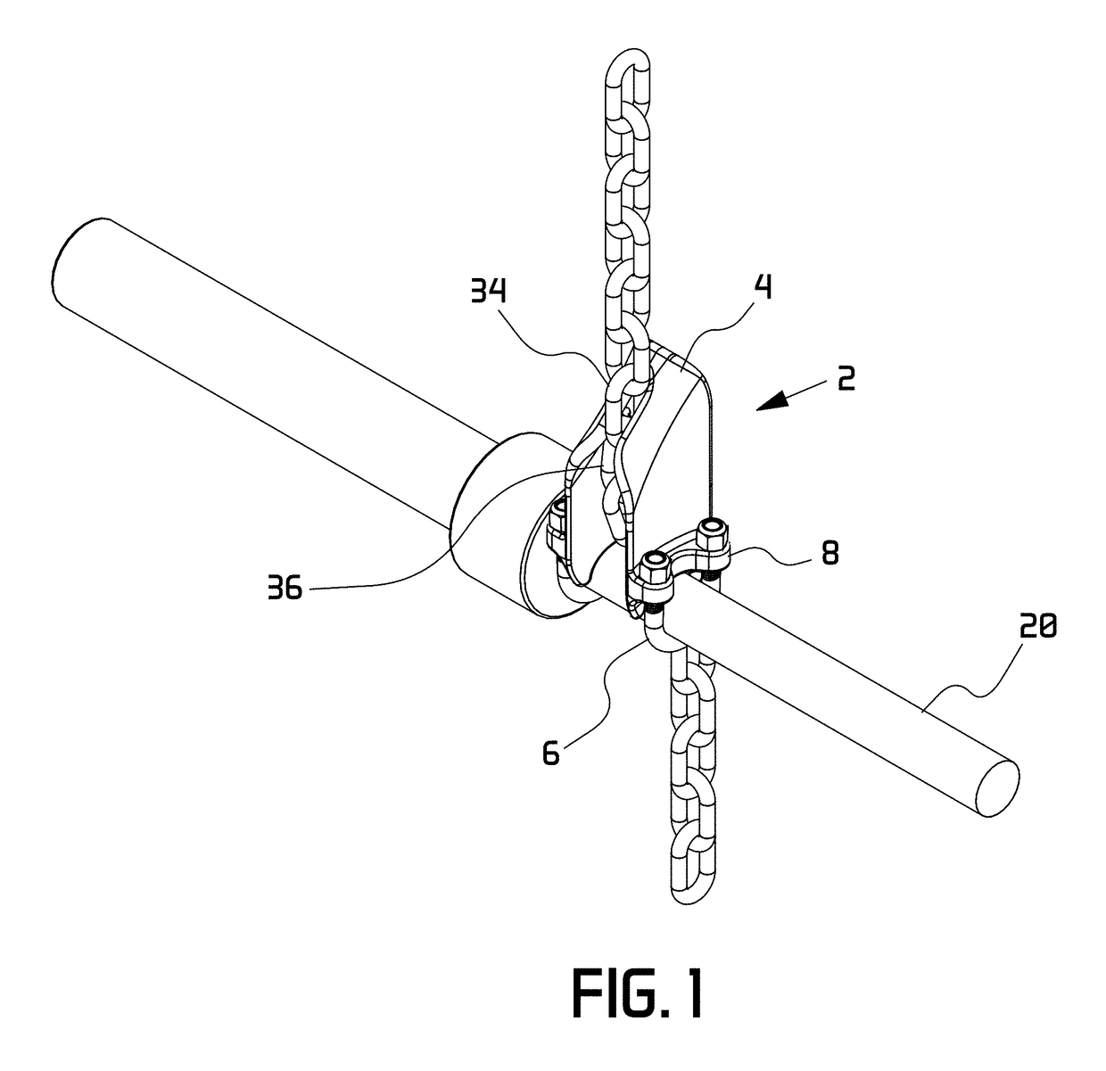
[0030]As used herein, the term “of a matingly conforming size” with respect to a chain for use with the chain trap, refers to a chain having individual links or rings that are sized for passage through the ovate opening of the chain trap's body, while the link or ring size prevents all adjacent links or rings (which are disposed generally perpendicular to all other adjacent links) from passage through the ovate opening. Stated in other terms, the chain has a thickness lesser than the width of the ovate opening but a width (the side to side measurement of the adjacent link or ring) that is greater than the width of the ovate opening.

[0031]As used herein, the term “unitary” refers to a one piece device or unit. Although it may be comprised of separate elements pe...


PUM


Abstract

A chain catch that is capable of being attached to various bases so as to allow the quick and simple affixation of the chain catch to any vertical chain. The chain catch has an upper body and a lower body. The upper body is designed to trap a vertical chain within its internal design while it remains within its vertical orientation, and the lower body is designed to attach to a load and to the upper body. When the tension is taken off of the chain within the chain catch and the upper body is tilted, the chain may be vertically raised, free from the chain catch or the chain catch and its attached barbell can be vertically raised.

Description

BACKGROUND OF THE INVENTION[0001]The present invention relates to a extremely compact apparatus for locking onto a metal or alloy chain. It is adapted to provide both safety and convenience for the user. In a suggested usage the apparatus may be incorporated into a weightlifting apparatus that allows weightlifters to solely perform exercises with heavily weighted barbells moving primarily in the vertical plane, but unrestricted in any axis of movement so as to provide a safe and truly free-weight lifting environment. It allows the barbell to be “racked” in a secure configuration so as to function as a self-spotting device, able to take the load of the barbell from the lifter at will.[0002]The American populace loves working out with weights. There has been a meteoric rise of small “boutique” personal training facilities in the last two years as the scientific study of weightlifting as applied to sports performance is big business now. However, many weightlifters still work out at ho...

Claims


Application Information

Patent Timeline
Patent Type & Authority Patents(United States)
IPC IPC(8): A47F5/00F16G15/00F16M13/02A63B21/078
CPCF16G15/00F16M13/02A63B21/0783A63B2225/093F16G15/04
Inventor JOHNSON, JOEL ANTHONY
Owner JOHNSON JOEL ANTHONY
Why Eureka
Try Eureka