Dental pressing furnace

Active Publication Date: 2018-03-20
IVOCLAR VIVADENT AG
View PDF14 Cites 1 Cited by
  • Summary
  • Abstract
  • Description
  • Claims
  • Application Information

AI Technical Summary

Benefits of technology

The dental pressing furnace invention provides improved means for measuring the temperature of a dental blank or other elements during the production process. By providing a temperature transmitter that can capture the temperature outside of the combustion chamber, the dental technician is no longer restricted by the temperature sensor in positioning the elements of the furnace. This facilitates the handling of the dental pressing furnace and allows for precise control of the furnace based on the temperature measurement. Additionally, the dental pressing furnace can be designed with the optical conductor coated parallel to the light guiding direction, which improves temperature measurement by preventing thermal radiation from the combustion chamber or the heating element from entering from the side. The dental pressing furnace can also be designed with a pressing rod and contact piston connected with a positive connection acting in the direction of the pressing force, which further supports temperature measurement by improving the optical transition between the two parts of the optical conductor.

Problems solved by technology

Depending on the starting temperature of the dental pressing furnace or the muffle, however, mispresses result from this process time and again.
Although it is possible with the help of the above-mentioned thermal element which is accommodated in the muffle to capture the temperature in the combustion chamber, it is of disadvantage that this thermal element is subjected to high temperature loads and mechanical loads in the combustion chamber of the dental pressing furnace, for which reason very cost-intensive sheath or jacket thermocouples must be employed here in order to allow a tolerably permanent use.
Irrespective of this, the handling of this thermal element which can be accommodated in the muffle is very problematic too.
Although the results of the temperature measurement within the scope of the dental pressing furnace mentioned are already satisfactory when the blank is separated from the optical conductor by pollutions or a wall of the pressing stamp, the best measurement results are only achieved with the help of the optical conductor if the optical conductor is guided directly up to the blank, such that the optical conductor entirely penetrates the pressing stamp.
In addition, aluminium oxide is brittle and has a coefficient of expansion that is within the range of coefficients of expansion of established materials which are used as blanks for the production of the dental restoration element.

Method used


Image

  • Dental pressing furnace
  • Dental pressing furnace
  • Dental pressing furnace

Examples


Embodiment Construction

[0026]In the Figures, equal technical elements are marked with equal reference numbers and are described only once.

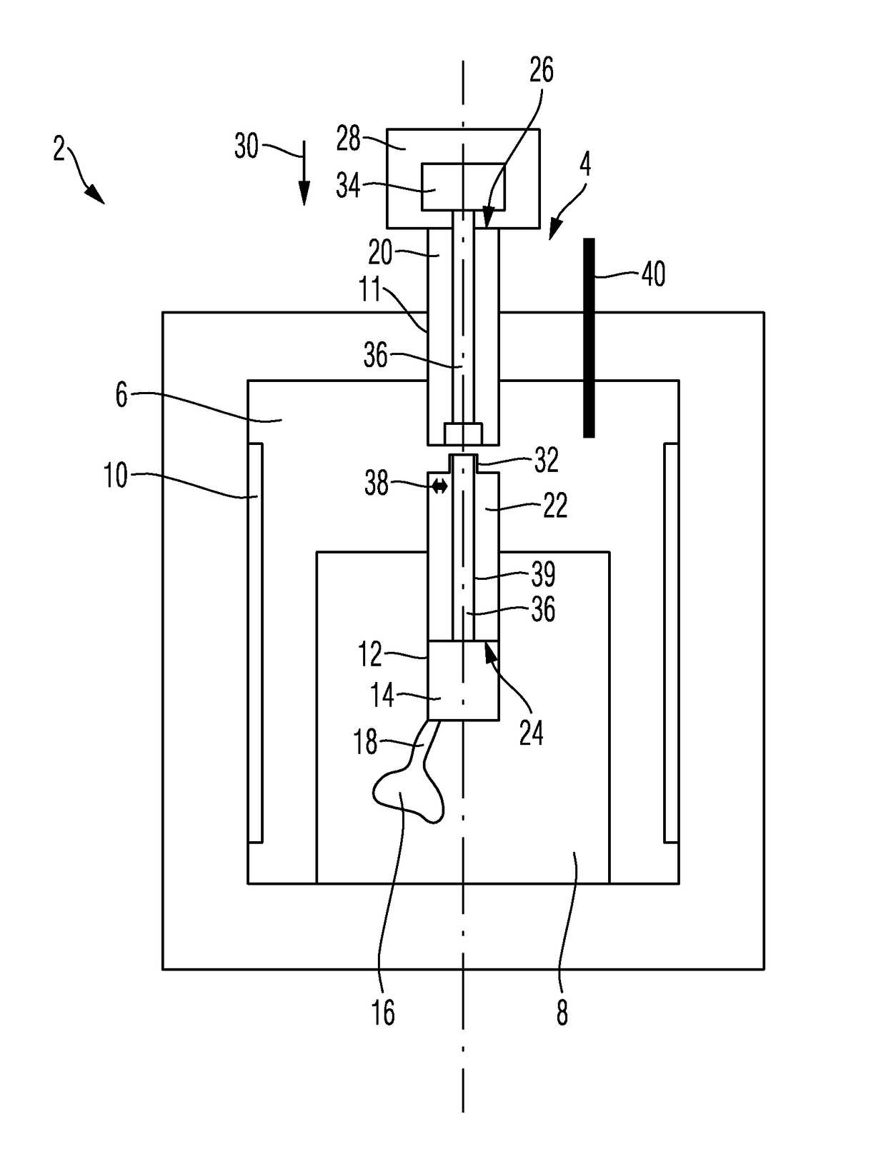
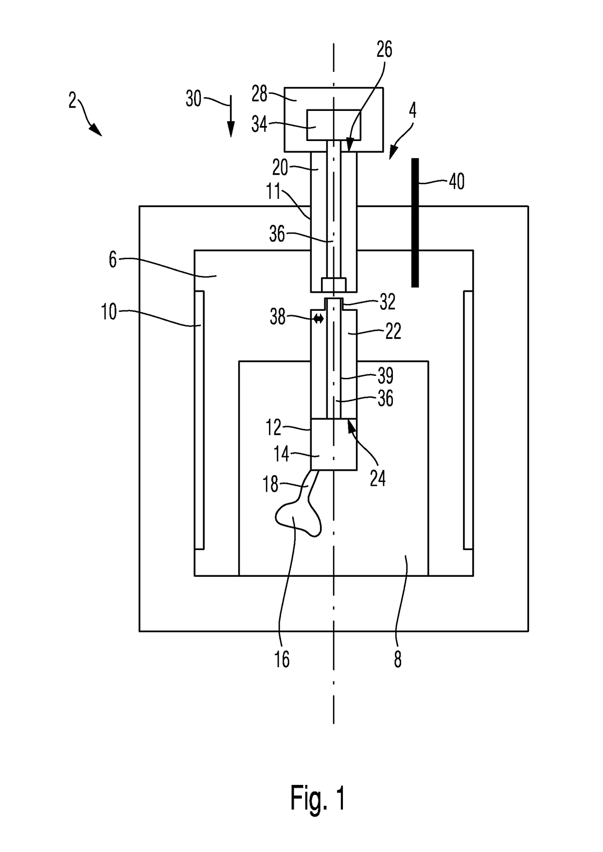
[0027]Reference is made to FIG. 1 which shows a dental pressing furnace 2 with a pressing stamp 4 in accordance with a first exemplary embodiment.

[0028]Dental pressing furnace 2 is provided, in a basically known fashion, with a combustion chamber 6 for accommodation of a muffle 8 as well as a heating element 10 arranged inside combustion chamber 6 for the purpose of heating up combustion chamber 6 and thus muffle 8. Combustion chamber 6 is provided with a guiding opening 11 guiding pressing stamp 4.

[0029]Muffle 8 is provided with an accommodation space 12 in which a blank 14 for producing a dental restoration element is accommodated. Muffle 8 is designed as an investment materials muffle in whose accommodation space 12 blank 14, for example in the form of a blank, in particular of a ceramic blank, is accommodated.

[0030]In muffle 8, at least one cavity 16 is provided in ...


PUM


Abstract

The invention relates to a dental pressing furnace for producing a dental restoration element in a muffle (8) by heating and pressing a blank (14). The dental pressing furnace comprises a combustion chamber (6), comprising at least one guide opening (11) that is opened towards the outside and a pressing stamp (4) guided in the guiding opening (11) and protruding into the combustion chamber (6) for applying pressing force to the heated blank (14) in the muffle (8). A temperature transmitter (36) guided at least in part by the pressing stamp (4) is configured to guide a temperature (50) of the blank (14) in the combustion chamber (6) from said combustion chamber, and a temperature sensor (34) connected to the temperature transmitter (36) outside of the combustion chamber captures the temperature (50).

Description

CROSS-REFERENCE TO RELATED APPLICATIONS[0001]This application is a National Stage application of International Patent Application No. PCT / EP2014 / 052279 filed on Feb. 7, 2014, which claims priority to European Patent Application No. 13157042.6 filed on Feb. 27, 2013, the disclosures of which are incorporated herein by reference in their entirety.TECHNICAL FIELD[0002]The invention concerns a dental pressing furnace with a pressing stamp, in accordance with the preamble of Claim 1.BACKGROUND OF THE INVENTION[0003]From DE 100 39 147 A1, a dental pressing furnace with a combustion chamber and a muffle accommodated in the combustion chamber with a cavity in the shape of a dental restoration element is known. Inside the combustion chamber, a blank in the form of a ceramic blank accommodated in the muffle can be heated up to a pressing temperature at which the blank becomes viscous, in order to press it into the cavity with the help of a pressing stamp. In order to determine the optimum mom...

Claims


Application Information

Patent Timeline
IPC IPC(8): A61C13/20F27B17/02F27D21/00F27B5/10F27B5/18
CPCF27B17/025A61C13/20F27D21/0014F27B5/18F27B5/10
Inventor JUSSEL, RUDOLF
Owner IVOCLAR VIVADENT AG
Why Eureka
Try Eureka