
Lacrimal duct tube

a technology of lacrimal ducts and duct tubes, which is applied in the field of lacrimal duct tubes, can solve the problems of poor therapeutic outcomes, failure of intra-lacrimal duct operations, and poor hardness, and achieves the effects of high hardness, reduced invasiveness, and reduced invasiveness

Active Publication Date: 2018-03-13
KANEKA CORP
View PDF34 Cites 0 Cited by
  • Summary
  • Abstract
  • Description
  • Claims
  • Application Information

AI Technical Summary

Benefits of technology

The present invention provides a lacrimal duct tube that allows for better visualization and manipulation in the lacrimal duct, with a reduced risk of damage or bleeding. The tube includes a plurality of resin portions with different hardness, with at least one positioned between the opening and the hole. The tube has a layered or aligned structure to enhance its ability to pass through lesions and reduce friction with the endoscope. The technical effects of the invention are improved maneuverability, enhanced visualization, and reduced risk of damage or bleeding.

Problems solved by technology

However, to insert the lacrimal duct tube, it is necessary to fumble for intra-lacrimal duct operations.
The bougies are blindly operated and thus may break through the tube or make a hole at a site other than in the normal lacrimal duct (creating a temporary path), which results in poor therapeutic outcomes.
In addition, occurrence of the disconnection may result in an unsuccessful surgery.
However, in the case of using the sheath guided endoscopic probing, the 1) lacrimal duct intubation instrument has a complicated tube structure, and the reinforcement body cannot be significantly smaller in diameter, and the extreme end of the tube is difficult to harden and thus tends to be slightly weak in pressing force (pushability).
In addition, when performing operations with the 1) lacrimal duct intubation instrument, it is necessary to carefully operate the endoscope inserted into the tube because friction between the lacrimal duct tube and the endoscope becomes large.
The 2) lacrimal duct treatment tool is entirely long, which tends to make it difficult to perform smooth operations in general.

Method used


Image

  • Lacrimal duct tube
  • Lacrimal duct tube
  • Lacrimal duct tube

Examples


example 1

[0122]Three-layer tubes with an outer diameter of 1.35 mm and an inner diameter of 0.95 mm were formed by multi-layer extrusion using an extruder such that a layer structure included: an inner layer with a cross-sectional thickness of 0.050 mm that was composed of high-density polyethylene with a Shore hardness of 72D (HB530 produced by Japan Polyethylene Corporation, the same thing can be applied to the high-density polyethylene with a Shore hardness of 72D described below); an intermediate layer with a cross-sectional thickness of 0.010 mm that was composed of a low-density polyethylene with a Shore hardness of 50D (PX3080 produced by Equistar Chemicals, the same thing can be applied to the low-density polyethylene with a Shore hardness of 50D described below); and an outer layer with a cross-sectional thickness of 0.140 mm that was composed of a mixture with a Shore hardness of 30D of polyurethane with a Shore hardness of 30D (Tecoflex EG85A produced by Noveon Inc., the same thin...

example 2

[0125]Two-layer tubes with an outer diameter of 1.31 mm and an inner diameter of 0.95 mm were formed by multi-layer extrusion using an extruder such that a layer structure included: an inner layer with a cross-sectional thickness of 0.080 mm that was composed of nylon 12 with a Shore hardness of 72D (Rilsan (registered trademark) produced by Arkema Inc., the same thing can be applied to the nylon 12 described below); and an outer layer with a cross-sectional thickness of 0.100 mm that was composed of polyamide elastomer with a Shore hardness of 40D (Pebax (registered trademark) 4033 produced by Arkema Inc., the same thing can be applied to the polyamide elastomer with a Shore hardness of 40D described below).

[0126]Cylindrical member with an outer diameter of 0.70 mm was formed from polyamide elastomer with a Shore hardness of 40D using an extruder.

[0127]The 40-mm two-layer tubes were arranged as tubular members on both sides. Then, the 25-mm cylindrical member was set as an intermed...

example 3

[0128]Two-layer tubes with an outer diameter of 1.31 mm and an inner diameter of 0.95 mm were formed by multi-layer extrusion using an extruder such that a layer structure included: an inner layer with a cross-sectional thickness of 0.080 mm that was composed of polyamide elastomer with a Shore hardness of 72D (Pebax (registered trademark) 7233 produced by Arkema Inc.); and an outer layer with a cross-sectional thickness of 0.100 mm that was composed of polyamide elastomer with a Shore hardness of 40D.

[0129]Cylindrical member with an outer diameter of 0.70 mm was formed from polyamide elastomer with a Shore hardness of 40D using an extruder.

[0130]The 40-mm two-layer tubes were arranged as tubular members on both sides. Then, the 25-mm cylindrical member was set as an intermediate connection member. The polyamide elastomers in the tubular members and the connection member were welded together. After that, the tips of the tubular members were thermally compressed and bonded to core ma...


PUM

PropertyMeasurementUnit
inner diameteraaaaaaaaaa
distanceaaaaaaaaaa

Abstract

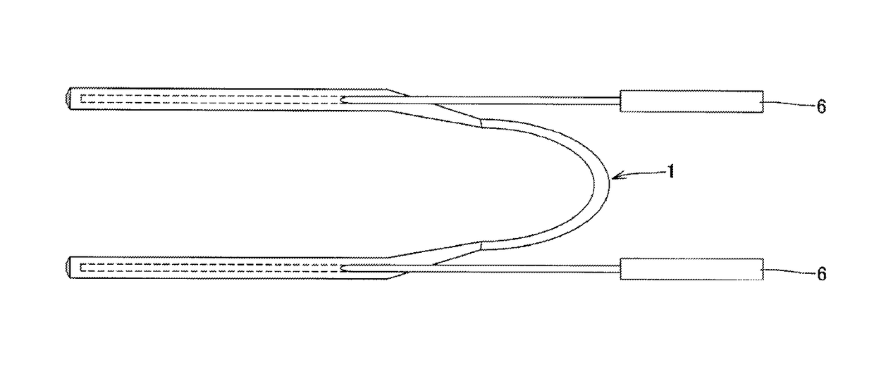
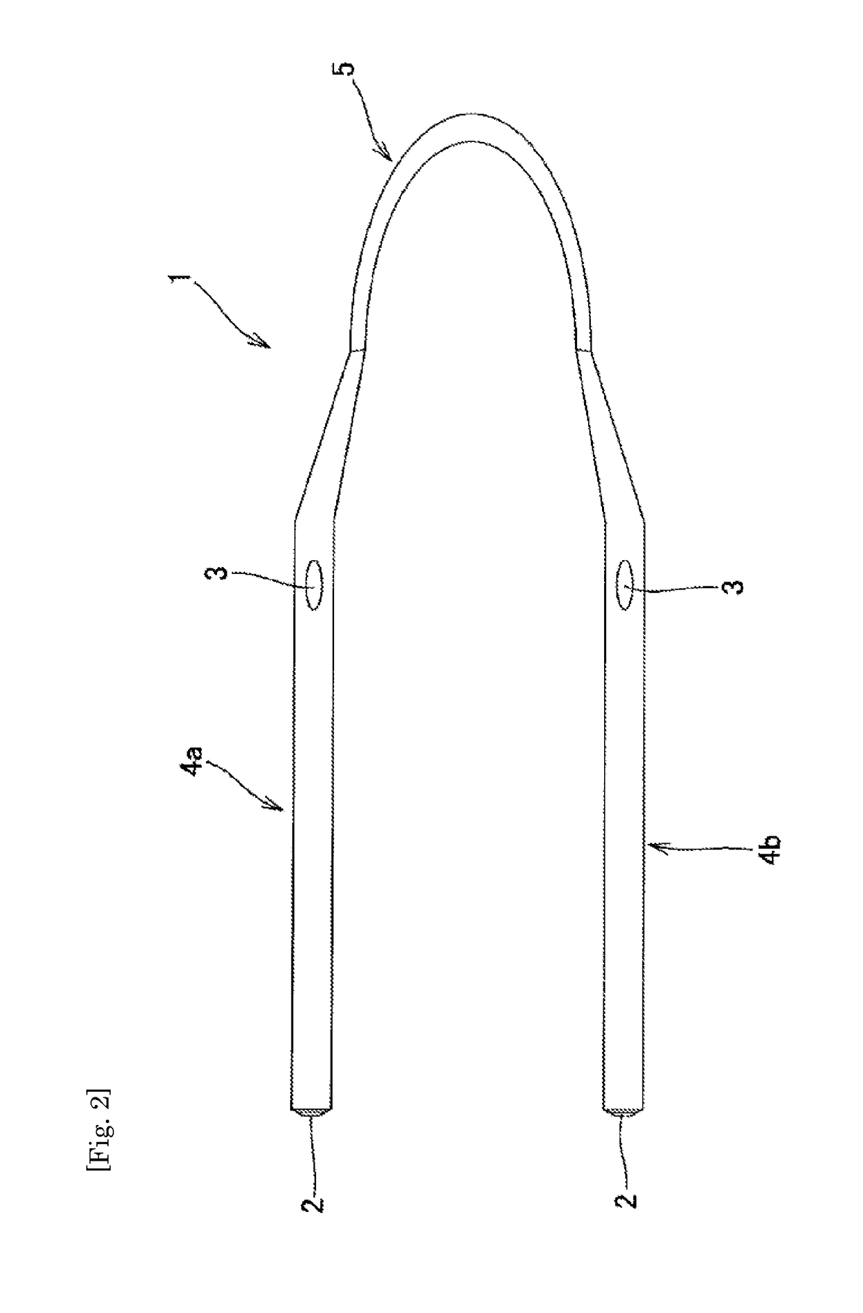
The present invention provides a lacrimal duct tube that can be preferably used for the treatment of lacrimal duct obstruction, in particular, sheath guided endoscopic probing having been frequently performed in recent years, the lacrimal duct tube being excellent in passage through a lesion in the lacrimal duct, operability in the lacrimal duct, and manipulation of the endoscope inserted into the lumen of the tube, and providing a sufficient viewing field of the endoscope. The present invention relates to a lacrimal duct tube, including: a pair of tubular members that each has an opening at one end and a hole in a side wall communicating with a lumen; and a connection member that connects other ends of the tubular members, wherein the tubular members each include a plurality of resin portions different in Shore hardness, at least one of the resin portions is positioned between the opening and the hole and forms a lumen wall of the tubular member, and the lumen wall has a Shore hardness of 57D or more.

Description

TECHNICAL FIELD[0001]The present invention relates to a lacrimal duct tube for use in treatment of lacrimal duct obstruction.BACKGROUND ART[0002]Treatment methods for lacrimal duct obstruction resulting in epiphora include: (i) probing by a lacrimal duct bougie, (ii) placement of a lacrimal duct tube; (iii) dacryocystorhinostomy (DCR); (iv) lacrimal canaliculization; (v) nasolacrimal duct plastic surgery; (vi) lacrimal caruncle moving surgery, and the like.[0003]The probing by a lacrimal duct bougie in (i) is intended to insert a narrow tube called bougie into a lacrimal duct to open an obstructed site and reconstruct a flow path for a lacrimal fluid. This method is conducted as a first treatment in many cases due to its ease of execution and minimal invasiveness. The treatments (iii) dacryocystorhinostomy (DCR), (iv) lacrimal canaliculization, (v) nasolacrimal duct plastic surgery, and (vi) lacrimal caruncle moving surgery are highly effective but relatively invasive because of the...

Claims


Application Information

Patent Timeline
Patent Type & Authority Patents(United States)
IPC IPC(8): A61M5/00A61F9/007A61L29/04A61L29/06A61L29/14
CPCA61L29/041A61L29/049A61L29/06A61L29/14A61F9/00772C08L23/06C08L77/00C08L75/04C08L53/02A61L2430/16
Inventor FUKAYA, KOHEIMIYAUCHI, HIDEKAZUMATSUMOTO, MARIKOOGINO, EIJIKOGA, CHIHIRO
Owner KANEKA CORP
Learn More